
 Zhejiang Hongyan Electric Co., Ltd.





































Power quality improvement in distribution system work on a plant feeder means correcting harmonic current, voltage swing, and reactive power on the circuit that feeds the drives, welders, and motors.
A single reading at one panel shows that something is wrong. It does not show whether the disturbance arrived from the utility side or from the machines. The path below separates a voltage sag from harmonic current, then matches a detuned reactor bank, HYSVG, or HYAPF to the load that is actually moving.
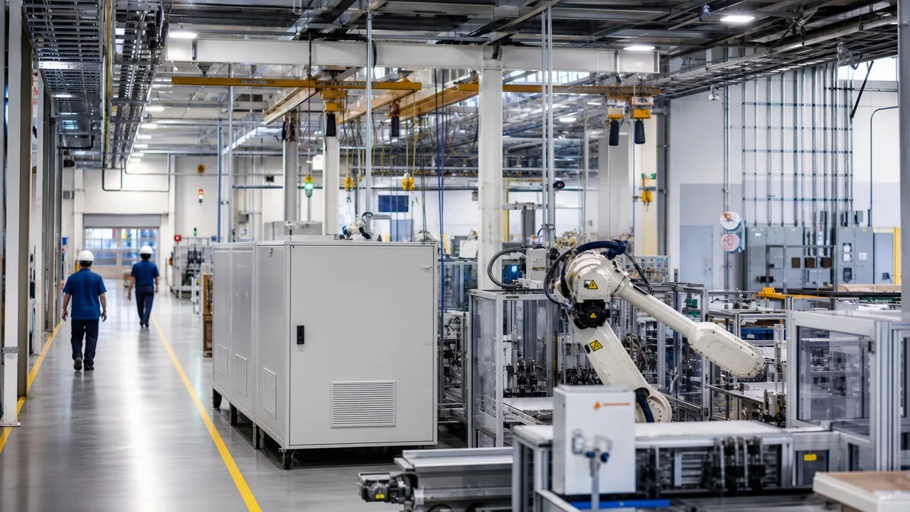
What a plant feeder is already carrying
A distribution feeder into an automated plant is already carrying three jobs at once: real power for the process, reactive power for motors and transformers, and harmonic current from drives and rectifiers.
Those three do not take turns. A welding line and a bank of variable-frequency drives can raise harmonic current in the same hour that compressors ask for more reactive power, and a sag on the incoming voltage can arrive while both are happening. The manufacturing plant page treats that mix as a common-bus problem, because judging one machine at a time misses the current that returns through the shared transformer.
A main-panel snapshot is a starting clue, not an origin. People who have logged a bad waveform often find the same trace whether the cause is upstream or inside the building, so the next measurement has to compare the service entrance with the bus that actually feeds the drives.
On this kind of feeder the buyer is not shopping for a definition. The buyer is deciding which of those three disturbances is large enough to buy hardware for, and which one is only riding along.
How voltage sag differs from harmonic current
A voltage sag is a short drop in RMS voltage. Harmonic current is extra current at multiples of the supply frequency, drawn by nonlinear loads and then forced back into the feeder impedance.
A voltage sag in the open chapter can last from half a cycle to 1 minute, and the average voltage falls by 0.1 to 0.9 pu. That dip is a supply event.
It is fixed, when it must be fixed, by adding the missing voltage in series with the load. Harmonic current is a load event. It is fixed by giving that current a local path, either a tuned branch or an active power filter that injects the opposite current.
Research papers use the name DSTATCOM for a shunt unit that can work in two modes. In current-control mode it goes after harmonic current, unbalance, and power factor.
In voltage-control mode it tries to hold the terminal voltage during a disturbance. Those are different control jobs, and a catalog unit has to be read for the job it actually states.
HYSVG is the shunt unit in this catalog for continuous reactive current. It is not sold under the DSTATCOM name, and it is not the series voltage device those papers call a DVR.
If the complaint is a controller resetting during a dip, harmonic current hardware will not restore the missing voltage. If the complaint is transformer heat and capacitor fuse operations while voltage looks ordinary, the sag story is the wrong one.
Where the harmonic check sits on the feeder
IEEE 519 harmonic limits apply at the user point of common coupling for the whole installation, in steady state. They carry no pass-fail stamp on one cabinet, and they are not automatically the right numbers at a panel deep inside the plant.
The point of common coupling is the handover with the supply, the place where the utility and the user can both see the same voltage and current. A study that only meters a drive output, or only meters inside a filter, can look calm while the handover current is still distorted.
The working-group note also says the limits are a steady-state checkpoint. A switching transient can sit outside them without rewriting the steady-state target.
That is why the measurement pack on the manufacturing solution asks for THD of voltage and current together with the single-line diagram and the transformer rating. The diagram shows where the handover is. The transformer rating shows the impedance the harmonic current has to push against.
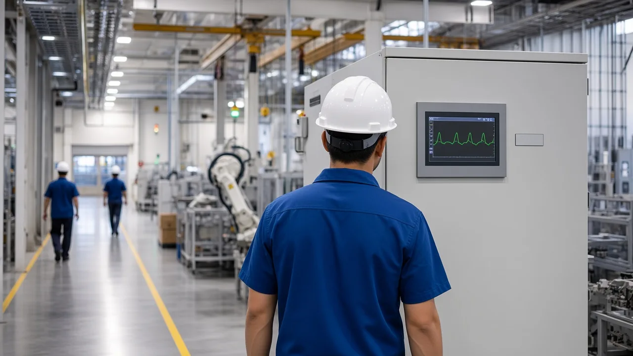
Bring both ends of the feeder into the same log. One capture at the service entrance and one capture at the drive bus, taken on the same production window, will show whether the distortion is arriving or being made. Without that pair, a new bank is a guess.
Why a plain capacitor step can magnify feeder harmonics
A capacitor bank is a low impedance at higher frequencies. Parked on a feeder that already has drive harmonics, it can tune with the supply impedance and magnify the very current it was meant to ignore.
The field report is blunt. On a feeder that served an induction furnace and large DC drives, capacitor-side power factor was reported moving from +0.96 to +0.55 once harmonic current reached the bank, and line current rose with it.
The reply on that thread said the practical fix is a detuned filter: a reactor and capacitor tuned just below the first predominant harmonic, the 5th for a 6-pulse drive and the 11th for a 12-pulse drive. The same reply warned that the capacitors already on site cannot simply be kept, because the series reactor raises the voltage on the capacitor terminals.
From the field: Furnace capacitors and large DC drives on one feeder were reported with power factor sliding from +0.96 to +0.55 — source: Eng-Tips, capacitor banks and harmonic issues.
That is the harmonic filter vs capacitor bank fork in plant language. A plain bank can still be right on a stiff feeder with little nonlinear load.
It is a poor fit once the drives are large enough to move the current spectrum. Blown capacitor fuses, a bank that runs hot, or a power factor that looks worse after the bank is switched in are the usual signs that the branch is interacting with harmonics instead of only supplying reactive power.
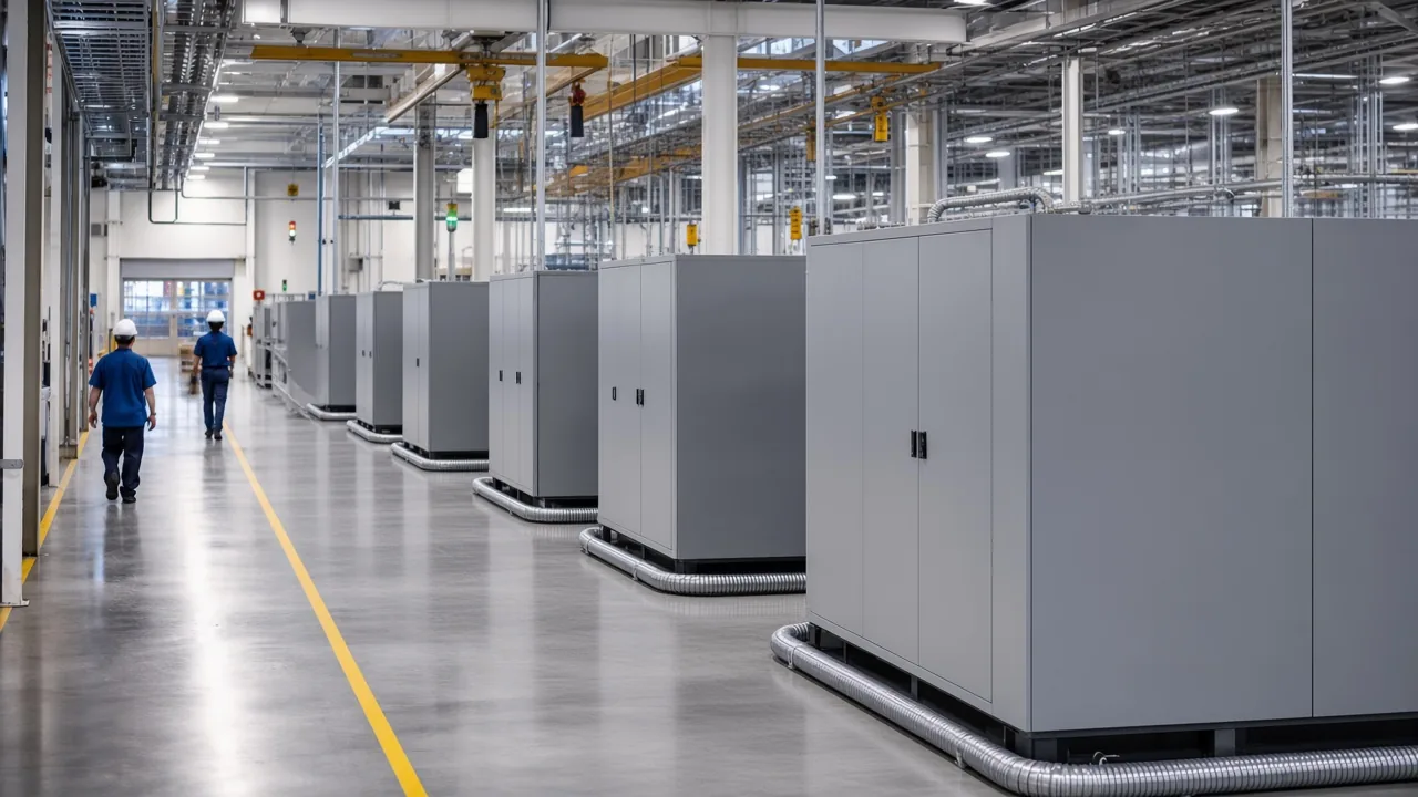
Another thread, from a plant that already had an active harmonic section, still asked why the power-factor capacitors had to be detuned. The answer there was the transformer.
Leakage inductance and the capacitor steps form their own resonance, often near the 5th, 7th, 11th, or 13th, even when a separate active unit is cancelling some of the load current. Detuning the capacitor branch does not become optional just because an active unit is in the room.
When a detuned reactor bank still fits
A detuned reactor bank still fits when the reactive power is fairly steady and the dominant harmonic order is known. The series reactor keeps the branch capacitive at power frequency, so it still corrects power factor, and it makes the branch inductive at the harmonic frequencies that were causing the trouble.
The series reactor page lists detuning rate options of 5.67%, 6%, 7%, and 14%. Those rates are the catalog steps for shifting resonance below the lowest harmonic order on that feeder.
A 6-pulse drive bus usually forces the conversation toward the lower rates, so the branch sits under the 5th. A 12-pulse bus can sit higher, under the 11th, which is the same split the forum reply used. The page also lists rated voltage from 230 V to 690 V at 50 Hz, for indoor reactors in the CKS-G and CKS-S lines.
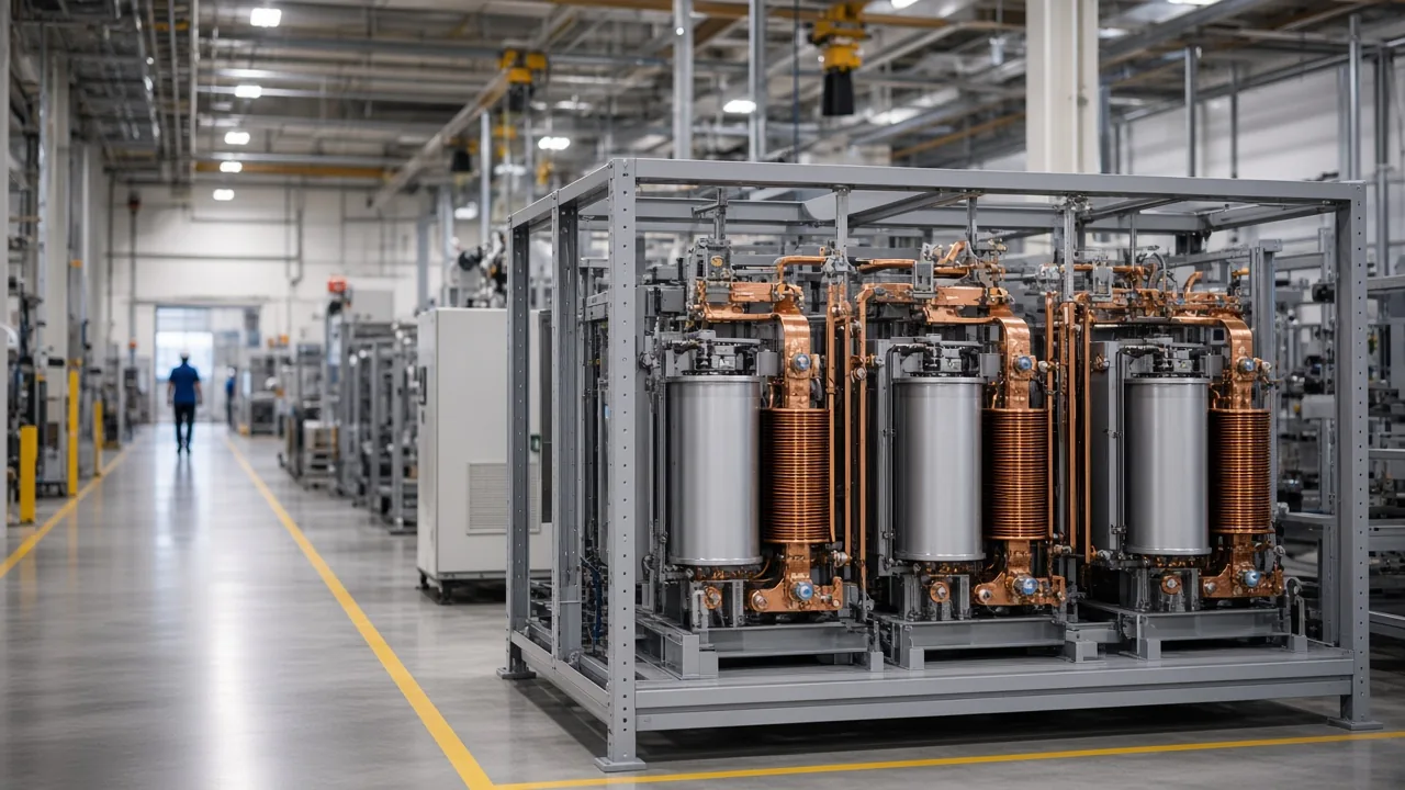
This is the right place for capacitor banks for reactive power compensation when the load chart is flat enough that stepped kvar will not hunt. Motors, compressors, and a steady furnace duty can live on that branch.
The branch is the wrong place when the production schedule swings kvar every few minutes, or when the harmonic orders themselves move because different drive groups start and stop. In that case the reactor still protects the capacitors you do install, and the moving part of the job goes to a unit that injects current.
Read the capacitor voltage again before reuse. Adding a reactor in series lifts the fundamental voltage on the capacitors, which is why a bank that was healthy as a plain step can be underrated once it is detuned.
New capacitors, sized for that rise, belong with the reactor. The manufacturing solution calls this the stable-compensation case, and it keeps the detuned bank in the configuration only where that description is true.
When the feeder needs injected harmonic current
The feeder needs injected harmonic current when the nonlinear load changes through the shift. An active power filter measures the load current and injects an equal and opposite harmonic current into the low-voltage network, so the upstream feeder carries a cleaner waveform.
HYAPF is offered at 400 V or 690 V. Its catalog response time is under 10 ms.
Order range sits beside the accuracy line. Compensation is stated from the 2nd order through the 51st. Catalog control accuracy is stated as THD under 5%.
The same unit can support reactive power and load imbalance, but its main job on this feeder is the harmonic current that a fixed branch cannot follow. Modules can be paralleled when the drive lineup grows.
HYSVG covers the adjacent job. HYSVG is rated 380 V.
Its full compensation time is 10 ms. It supplies inductive or capacitive reactive current continuously, without the switching transient of a capacitor step, and the catalog lists 50 kvar, 75 kvar, 100 kvar, and 200 kvar frames with parallel expansion.
Use it when welders, hoist cycles, or drive starts make reactive power move faster than a stepped bank should switch. Use HYAPF when the waveform, not the kvar, is what the transformer and the handover current are suffering.
| Disturbance on the feeder | What it looks like in the log | Hardware role that matches |
|---|---|---|
| Steady reactive power, known harmonic order | Power factor lag, stable spectrum | Detuned reactor with capacitors |
| Reactive power that swings with the machines | kvar and voltage moving every start | HYSVG continuous reactive current |
| Harmonic current that changes with the lineup | THD and neutral or phase current moving with production | HYAPF opposing harmonic current |
| Short voltage drop at the handover | RMS dip while load current is ordinary | Series voltage support |
| Catalog item | Stated electrical point | Stated speed | Feeder job |
|---|---|---|---|
| Series reactor branch | Detune options 5.67%, 6%, 7%, 14% | Stepped with the bank | Stable kvar, resonance moved down |
| HYSVG | 380 V, continuous inductive or capacitive | Full compensation 10 ms | Fast reactive current, no capacitor step |
| HYAPF | 400 V or 690 V, 2nd through 51st | Response under 10 ms | Changing harmonic current |
The two tables are the same decision in two views. The first view starts from the log.
The second view starts from the nameplate. If they disagree, trust the log. A 10 ms reactive unit does not cancel a moving harmonic spectrum by itself, and a detuned bank does not follow a welding schedule.
How to select a manufacturing plant power quality solution
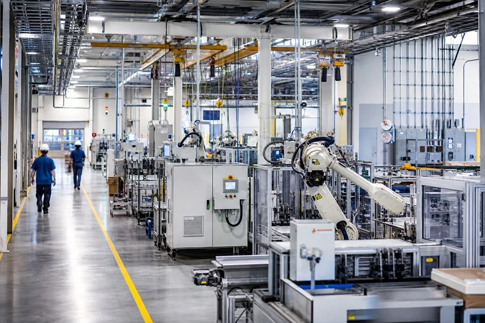
Select the manufacturing plant power quality solution when one feeder mixes drives, welding, rectifiers, compressors, and motors, and the three roles have to be coordinated at the common bus.
The page already splits the work the way the measurements split it. Active harmonic filters take the changing low-voltage nonlinear loads.
SVG takes fast reactive power and phase imbalance. Detuned capacitor banks stay where compensation is stable.
That is a fit test, and the page does not force every role into one order. A plant whose log shows only a stable lagging power factor and a known 5th can stop at the series reactors and the capacitors sized for them.
A plant whose reactive current slams around, with a calmer waveform, goes to the HYSVG static var generator. A plant whose harmonic current tracks the production schedule goes to the HYAPF series active power filter.
What to bring to that page is the same pack the solution already lists: the single-line diagram, transformer ratings, the load list, VFD and welding capacities, measured voltage and current distortion, the operating schedule, the target power factor, and any expansion already planned. Those inputs decide capacity and connection point. They also stop a detuned bank, an SVG, and an active filter from being stacked because each brochure sounded useful.
Leave this solution page when the real problem is a series voltage dip on a sensitive controller and the current waveform is already acceptable. Harmonic and reactive hardware on the feeder will not insert the missing voltage.
Leave it also when the only goal is a software dashboard. Monitoring can show the entrance-versus-bus split, and it does not inject the current the feeder is missing. CHYN's hardware for this job is the filter, the var generator, and the detuned branch, coordinated on that manufacturing solution.
A lateral comparison of filter and bank behavior sits in the harmonic filter vs capacitor bank note. Use it when the only open question is that fork. Come back here when the feeder also has swinging reactive power or a sag that must not be confused with harmonic current.
FAQ
Does a shunt compensator correct feeder current and feeder voltage at the same time?
Not in one control mode. Current-control mode works on harmonic current, unbalance, and power factor.
Voltage-control mode is the one that tries to hold terminal voltage during a disturbance. Read the catalog for the mode and the job that are actually stated.
HYSVG states continuous reactive current. HYAPF states harmonic current injection.
Can monitoring software inject the current a feeder harmonic problem needs?
No. A meter, a logger, or a dashboard can show sags, harmonics, and imbalance, and it can help separate the service entrance from the drive bus.
Injection takes a power circuit: an active power filter, a reactive-current unit, or a detuned capacitor branch. Software that only displays the waveform leaves the feeder current where it found it.
Why do power-factor capacitor fuses open after drives are added?
The new harmonic current can tune with the capacitor bank and the supply impedance. The bank then carries more high-frequency current than it was sized for, fuses open, and the power factor you bought the bank for gets worse. A series reactor that places resonance below the dominant drive harmonic is the usual correction, with capacitors rated for the higher terminal voltage.
Where should reactive compensation sit relative to the drives?
Close enough that the feeder and the transformer are not carrying the whole reactive current, and visible on the single-line so the resonance with transformer leakage can be checked. On a mixed manufacturing feeder that point is the common bus, not a random machine terminal and not only the utility meter. The drive bus and the service entrance should both be in the measurement, or the bank will be placed on a guess.
Does IEEE 519 judge a single cabinet or the point of common coupling?
It judges the installation at the point of common coupling, in steady state. A quiet nameplate inside a filter cabinet is not the checkpoint.
A transient can exceed the steady-state picture without becoming the design target. Inverter-based resource limits are pointed at other documents and are not a sticker on this hardware.
What happens to power factor when many small motors run lightly loaded?
Displacement power factor falls, because the motors still draw magnetizing current while they deliver little real power. A plant that expected drives alone to hold a high power factor can sit near 0.87 for that reason, even with an active harmonic section already installed. The detuned capacitor question remains, because transformer inductance and the capacitor steps can still resonate.
Is a series voltage injector the first hardware choice for feeder harmonic current?
No. A series injector is the tool for a voltage sag or swell, where the missing or extra voltage has to be added in series with the load.
Feeder harmonic current is a shunt problem. Start with a detuned branch when the order is stable, or with an active power filter when the spectrum moves, and add HYSVG when the reactive current is what swings.
References
- IEEE Harmonics Working Group, IEEE 519 development note, on where voltage and current distortion limits apply
- Kanchanapalli and Banka, Power Quality Improvement in Distribution System, IntechOpen, on sag duration and series versus shunt devices
- Eng-Tips discussion, capacitor banks and harmonic issues, on detuning below the predominant drive harmonic