
 Zhejiang Hongyan Electric Co., Ltd.





































A shunt capacitor bank supplies leading reactive power next to inductive load, so upstream current falls and the network sees four effects at once: power-factor or kVA billing relief, released transformer and cable capacity, voltage support on the feeder, and lower I²R heating. Those advantages of using capacitor bank in a power system show up on industrial feeders whose lagging reactive demand is reasonably steady and whose harmonics have been checked, not on every bus that looks “low PF” on a handheld meter.
The buy-or-don't-buy scorecard, including failure modes and when not to purchase, lives in capacitor bank advantages and disadvantages. Hardware families sit in the high-voltage power factor compensation series.
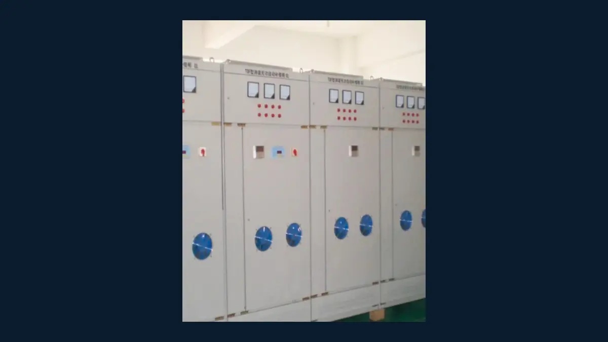
What a Power System Gains from Local Capacitive Vars
A shunt capacitor bank supplies leading vars at the connection point so the rest of the power system carries less lagging current; the four system gains are billing relief, thermal headroom, voltage support, and lower I²R loss.
Reactive power (kvar) is the non-working part of apparent power that magnetises motors and transformers. The plant borrows that current every cycle and hands it back; hanging capacitors on the bus makes the exchange locally instead of shipping it through every feeder and transformer upstream.
This is not bulk energy storage. Ranking pages sometimes talk as if a bank stores surplus kilowatt-hours and releases them later; a power-factor bank does not replace a battery, and that comparison belongs on a different page.
| System advantage | Where it appears | Cue it is already visible |
|---|---|---|
| PF / kVA billing relief | Utility meter and demand line | PF surcharge or kVA demand high while kW looks ordinary |
| Released transformer and cable capacity | Thermal path upstream of the bank | Transformer or cables hot at moderate real load |
| Voltage support | End of a reactive feeder | Lights dip or contactors chatter when large motors start |
| Lower I²R heating | Conductors and windings carrying the old current | Feeder cables warmer than the kW would suggest |
Power Factor and Billing Relief on the Supply Meter
Advantages show up as cash when the tariff charges poor power factor or bills kVA demand; the useful target is the tariff threshold, not unity.
Displacement power factor is the ratio of real power to fundamental apparent power after phase shift. Apparent power (kVA) is what the meter and the transformer both see: the vector sum of kilowatts and kilovars. Cut the lagging vars at the plant, and that hypotenuse shortens.
Many industrial tariffs make the advantage explicit with a PF penalty. Others hide it inside a kVA demand charge, so a lagging plant pays for ampacity the utility had to build even when nobody named a “power factor fee.”
Works engineers who have stood in front of a kvar-hour meter already know the pattern: the bill is the first place the advantage is supposed to appear, and it only appears downstream of the meter if the bank sits on the plant side of that meter.
Chasing a perfect 1.0 is usually the wrong stop. Community answers on industrial commissioning treat a lagging reading around the utility’s surcharge line as good enough, because extra steps spent closing the last gap buy leading power factor at night more often than they buy another dollar.
Released Transformer and Cable Capacity
Lower current frees kVA in equipment upstream of the bank, and the gain is largest when the bank sits near the inductive load. That released transformer capacity sits in the iron and copper already paid for, not in extra kilowatts.
Cables and transformers are sized for apparent power, not for kilowatts. Lagging current occupies ampacity that never turns into product; remove that current and the same iron and copper can carry more real load.
Practitioners describe the same effect as increased load-carrying capability in existing circuits, and as a chance to avoid a larger transformer on a new installation. The physics is directional: capacitors help everything from the point of installation back toward the source, so a bank at the motor or MCC frees more of the plant feeder than a bank left at a remote substation.
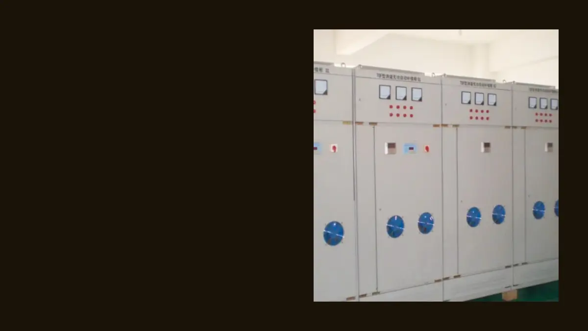
A plant told that “the transformer is full” while kilowatt demand still looks moderate is usually looking at this advantage in reverse. The nameplate is full of amps, not of finished tons.
Voltage Support Along Industrial Feeders
Removing reactive flow cuts the reactive share of feeder voltage drop, so voltage at the connection rises and the profile along the run flattens. That capacitor bank voltage support is the Q·X term shrinking, rather than a wall-mounted regulator.
Approximate drop along a feeder has both a real term and a reactive term. On many industrial and distribution runs the reactance term dominates, so cancelling lagging vars removes a large piece of the sag that motors create at the far end.
Utilities switch capacitor banks on at peak load for the same reason: hold the distant bus up when the feeder is heavy, then drop steps at light load so voltage does not climb. An automatic plant bank follows the same logic on a shorter cable.
Important: shunt capacitor output falls with the square of voltage — least vars when the bus is already depressed. When the bus is already down, the bank delivers fewer vars at the moment the feeder wants them most, so voltage support is an advantage of a healthy connection, rather than a rescue for a collapsed bus.
A larger bank on a weaker short-circuit level also produces a larger voltage rise. That is useful headroom on a sagging feeder and a nuisance if the same steps stay in overnight.
Lower I²R Heating in the Current Path
Heating in conductors and windings falls with the square of current; that mechanism is real, and it is never a published energy-saving percentage for the plant. People name it I²R losses power factor correction; it is still copper heat falling with current squared.
I²R loss is ordinary copper heating. Cut line current by a modest fraction and the heat falls faster than the current, which is why loss reduction is easy to undervalue if someone only looks at the amp reading.
From the field: welders and other lagging machines often publish two input currents, with and without power-factor capacitors — operators treat the lower figure as the current the supply actually has to carry. That is the same current cut that cools a plant feeder, never a promise that kilowatt-hours on the energy meter will drop by a quoted percent.
The advantage accrues every hour the reduced current flows upstream of the bank. Place the bank at the substation and the plant cables keep their old heat; place it at the load and the plant cables are in the current path that shrank.
Keep that physics off the catalogue as an efficiency claim. No CHYN plant measurement is quoted here, and classroom worked examples stay unpublished.
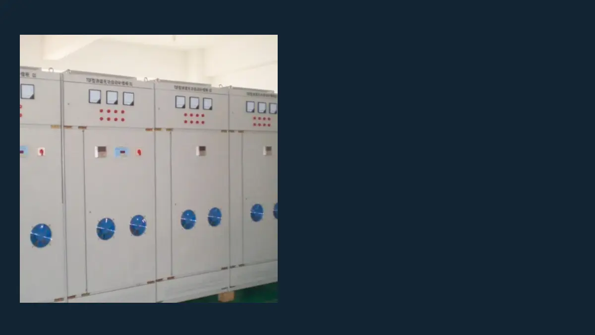
When Those Advantages Show Up on Industrial Feeders
The four gains appear on feeders with a measurable lagging reactive demand, a bank close to that load, steps that can follow the shift, and a harmonic picture that will not ring with the capacitance.
A day-shift motor plant with a lagging displacement power factor is the clean case. Detuned capacitor banks remain appropriate there when compensation is stable, which is how first-party manufacturing guidance already splits the duty from active filters and fast reactive machines.
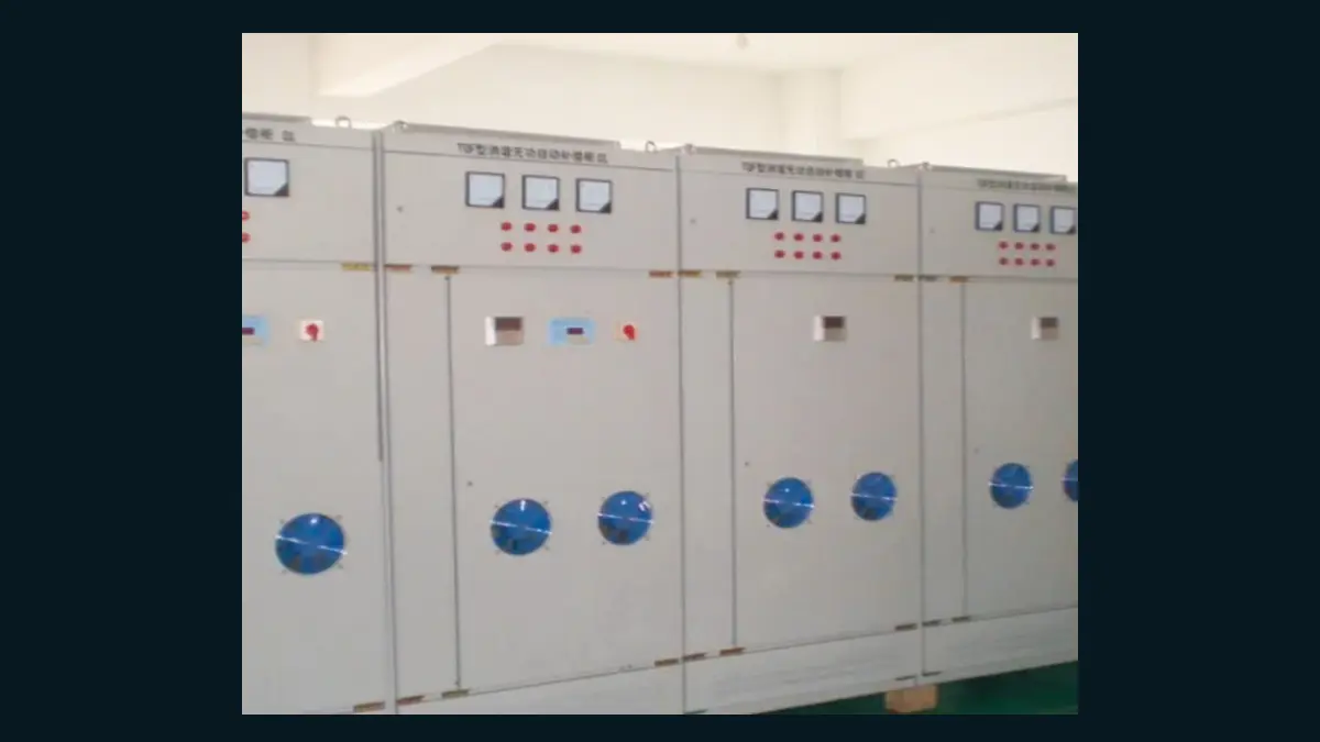
Keep large fixed steps connected around the clock and the night shift invents a leading power factor. Voltage climbs, the billing advantage can reverse, and the thermal headroom story no longer matches the quiet plant.
Tip: a plain shunt bank does not “reduce harmonics.” — vendor pages list that as an advantage; on a drive or furnace bus the same capacitance can move a resonant point onto an order the load already produces. Filter branches and detuning are different equipment.
| Feeder picture | What still holds | What to open next |
|---|---|---|
| Steady lagging motors, clean-enough spectrum | PF, capacity, voltage, I²R | Shunt / detuned bank RFQ, e.g. HYTBB outdoor box type |
| IF furnace with 5th, 7th, 11th current | Same four gains only if branches are tuned | HYFC-ZP below |
| Fast-swinging melt or mill reactive duty | Base shunt compensation only if a harmonic study permits | Fast reactive equipment instead of switched shunt steps |
Steel-plant guidance says the same thing in one line: high-voltage capacitor banks for stable base compensation where the harmonic study permits.
When to Select and Recommend HYFC-ZP Filter Compensation
Select HYFC-ZP when the power-system advantage story is an intermediate-frequency furnace plant that still needs the PF, capacity, voltage and loss gains, but cannot take them from a plain shunt bank because of characteristic harmonic current.
An IF furnace is a nonlinear melting load. The published page states a typical natural power factor around 0.80–0.85, with higher-power units often 0.88–0.92 without compensation and still a large reactive demand, and names the 5th, 7th and 11th as the main harmonic orders.
A tuned filter branch is a reactor-capacitor branch sized to those orders so the cabinet absorbs harmonic current while it still supplies vars. That is how the four system advantages survive on a furnace bus instead of turning into resonance.
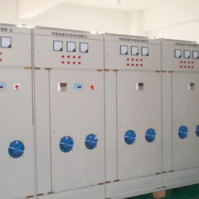
The HYFC-ZP Series Passive Harmonic Filter & Energy-Saving Compensation Device for Intermediate-Frequency Furnaces is the catalogue match for that feeder. Published envelope: rated voltage 400 V, 525 V, 660 V, 750 V and 1000 V; capacity 120–20,000 kVAR; power factor after compensation 0.90–0.99 depending on configuration; indoor; ambient −15 °C to +45 °C. After restoration, compensation resumes in about 5 seconds, with reactive deviation held within ±10% of rated reactive power.
Recommend HYFC-ZP for IF-furnace filter plus energy-saving compensation. For a 6–10 kV substation that only needs a shunt capacitor bank, enquire on the HYTBB Series Medium & High Voltage Reactive Power Compensation System – Outdoor Box Type page; that pointer is a live product URL, never a claim that the recommendation photo is HYTBB hardware.
Treat the catalogue envelope as published ratings, not field-test, certification, or service-life evidence. Send voltage, furnace rating, measured spectrum and target power factor with the enquiry.
FAQs
Why do we use a capacitor bank in a power system?
To supply leading reactive current locally so generators, lines and transformers stop carrying lagging current they cannot bill as useful work. The system-level return is PF or kVA relief, freed ampacity, voltage support and lower I²R heating.
Does a capacitor bank save electricity?
It can cut I²R heating in the path upstream of the bank because losses follow current squared. It does not turn kilowatts of process load into a guaranteed energy-saving percentage on the kWh meter.
Do the advantages include lower harmonics?
No for a plain shunt bank. Capacitance can land on a harmonic the plant already makes. Lower distortion is a filter-branch job, which is why an IF furnace page is not a generic capacitor-step page.
On which industrial feeders do the advantages actually show up?
On feeders with lagging reactive demand that stays put long enough for steps to follow, with the bank near that load, and with a harmonic check that says the capacitance will not ring. Night-shift leading PF and unmeasured drive buses are the usual ways the story fails.
Should the plant correct all the way to unity power factor?
Usually not. Industrial commissioning discussion treats getting above the utility’s lagging surcharge line as the cash target. Closing the last gap often means extra steps that run leading when the plant goes quiet.
When should an IF furnace plant not buy a plain shunt bank?
When the bus already carries the furnace’s 5th, 7th and 11th current. The plant still wants the four system advantages, but it needs tuned branches that absorb those orders while they supply vars.
Where is the full advantages-and-disadvantages / when-not-to-buy discussion?
In the live companion capacitor bank advantages and disadvantages. That page owns cost, resonance, overcompensation and the purchase judgement; this page owns the system-advantage map.
Does placing the bank at the substation capture the same loss and capacity advantages as placing it at the plant?
Only for the network upstream of the substation. Plant cables and the service transformer keep carrying the old reactive current unless compensation sits on the load side of those assets.
References
- Capacitor Banks in Power Systems (GIEE) — local kvar supply, current and I²R relationship, feeder voltage drop, and placement at plant, motor or feeder.
- Benefits of Adding Capacitors to the Electric System (NYISO / Quanta) — loss reduction and released feeder capability as primary distribution benefits of capacitive support near inductive load.
- Capacitor Banks | IEEE Technology Navigator — local reactive supply, industrial power factor, voltage rise with bank size, and filter banks on furnace and drive installations.
- Power factor (Wikipedia) — demand charges for poor power factor, loss and voltage effects of correction, and why reactive elements still need engineering on the bus they sit on.
- Power factor correction and harmonic resonance (Mike Holt Forum) — installing contractors describe swollen cans and fuse operations when plain correction is added on drive-fed buses, which is why “lower harmonics” is refused as a shunt-bank advantage.