
 Zhejiang Hongyan Electric Co., Ltd.





































shunt active power filter matlab simulink model is a control-study canvas: it shows p-q or SRF scopes on a laptop, and it does not push opposing harmonic current onto a plant bus. A teaching file is enough while the job is still coursework. Hardware belongs on the bus when crushers, mills, or VFDs already distort current.
The blocks below, the split between p-q theory and the synchronous reference frame, and the published LV cabinet are how that call is made. Catalog hardware sits on the Active Power Filter Series hub; CHYN does not ship a MATLAB/Simulink model.
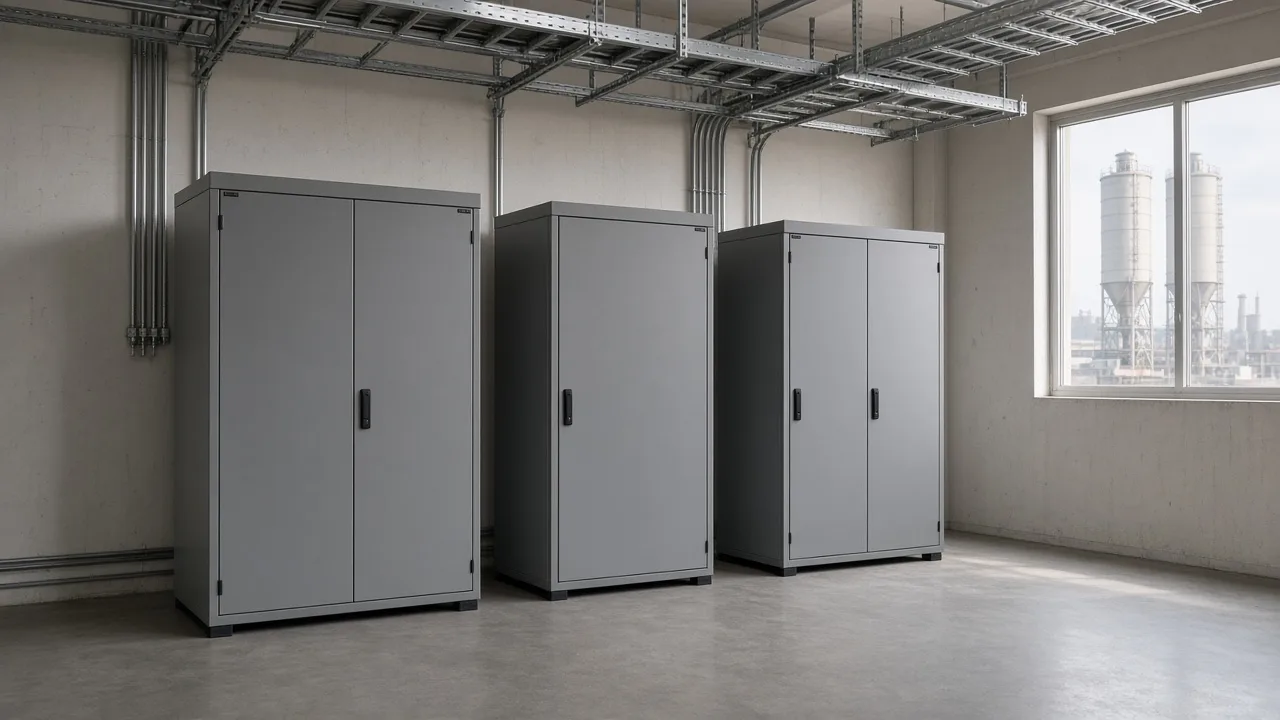
What a Simulink shunt APF model is actually for
It is a teaching canvas for control study; it does not inject plant current. Students open a three-phase or single-phase file to watch a nonlinear load, a controller, and a scope, then stop when the waveform on the screen looks cleaner.
File listings of that kind walk Clarke math, filter the constant part of instantaneous power, and fire a hysteresis band so a simulated inverter pushes compensating current into a simulated line. Seeing how active harmonic filter works on that canvas is still a lab exercise. The mill bus outside the window does not change.
A fixed trap only removes the orders it was tuned for, and it can resonate with the supply. That is why teaching files exist. They are the wrong object once the same current is already on a crusher MCC and someone needs amperes on copper.
| Job in front of you | What belongs | What stays off the purchase order |
|---|---|---|
| Coursework, controller debug, FFT of a rectifier block | A shunt active power filter MATLAB/Simulink model | Cabinet amperes, CT ratio, enclosure |
| Harmonic current already on a plant bus | Hardware that injects the opposite current | Another .slx download |
| Vars or unbalance only, spectrum steady | A different compensator class, studied separately | Treating a scope plot as a nameplate |
Which blocks a teaching SAPF canvas analogizes
Those four blocks are what the model is standing in for: a controller, an inverter, a DC capacitor, and a coupling inductor. The MATLAB/Simulink model draws them so a student can see signal flow without standing in a switchroom.
A voltage source inverter builds the compensating wave from the DC-link capacitor the AC line keeps charged. A coupling inductor sits between that inverter and the bus so the bridge does not hard-short the feeder. Hysteresis current control is the usual teaching switcher: a band around the current error flips the gates, and the switching rate moves with the error.
Clarke transformation is the first math step on most three-phase canvases, taking phase currents into an alpha-beta frame before p-q or dq work. None of those blocks, drawn on a screen, is a nameplate.
How p-q and SRF differ on the canvas
Both estimate compensating current; they are identification exercises, not product names. p-q theory turns voltages and currents into instantaneous real and imaginary power, keeps the average real power the supply should deliver, and inverse-transforms the leftover into a current reference.
The synchronous reference frame parks the fundamental with a PLL, then a low-pass filter holds that DC piece so the AC leftover can be the harmonic reference. Direct power, direct current, and indirect current variants in the same teaching zip are switches you enable one at a time. Changing the switch does not change the plant.
From the field: after Clarke, PLL, and Park, the missing block was a low-pass filter near grid frequency; subtract the fundamental it passes and the harmonic leftover remains. — Electronics Stack Exchange
Capstone builds often get reactive and unbalance references moving, then stall on harmonic injection because the 5th is negative sequence and the 7th is positive sequence. A fundamental PLL angle does not automatically frame both.
| Identification on the canvas | What the student is practicing | What it does not set |
|---|---|---|
| p-q theory | Split average real power from oscillating power and imaginary power | Cabinet current rating |
| Synchronous reference frame | Low-pass the dq fundamental, invert the leftover | CT location on a mill one-line |
| One method at a time in a shared file | Compare controllers on the same rectifier block | Which plant bus gets hardware |
What a student THD plot does not size
A rectifier-block FFT is that model’s result, not the mill ampere rating. One published MATLAB/Simulink rectifier case at 480 V reported current total harmonic distortion of 25.75% before the filter and 4.87% after.
Those two percentages belong to that paper’s source, rectifier, and DC link. Copying them onto a purchase line guesses the crusher current. A listing that quotes a still-lower source THD is the same class of evidence: a scope on a simulated line.
Total harmonic distortion on a stiff teaching source can fall while the plant transformer still heats, because plant impedance and load cycle were never in the file. Harmonic injection failing after vars already look fine is a controller problem on the canvas, not proof the cabinet class is wrong.
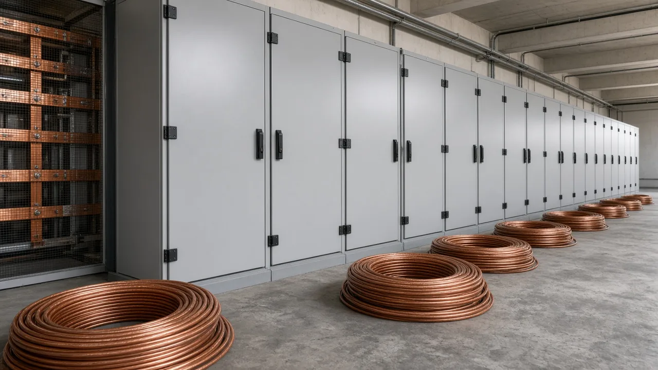
When the job leaves the laptop for plant current injection
Hardware is required when opposing harmonic current must enter the point of common coupling. A shunt active power filter sits in parallel with the nonlinear load and injects current equal in magnitude and opposite in phase to the harmonic part the load draws.
The supply then carries more of the fundamental. Reactive current and phase balance can share that same injection, up to the ampere budget of the cabinet. Multiple shunt units can be paralleled when one frame’s current is not enough.
A low-pass filter near 50/60 Hz is the block that keeps the fundamental and leaves the harmonic leftover on a teaching canvas. On the plant, that leftover is a current the cabinet must be able to produce, measured on the real load cycle rather than on a universal-bridge block.
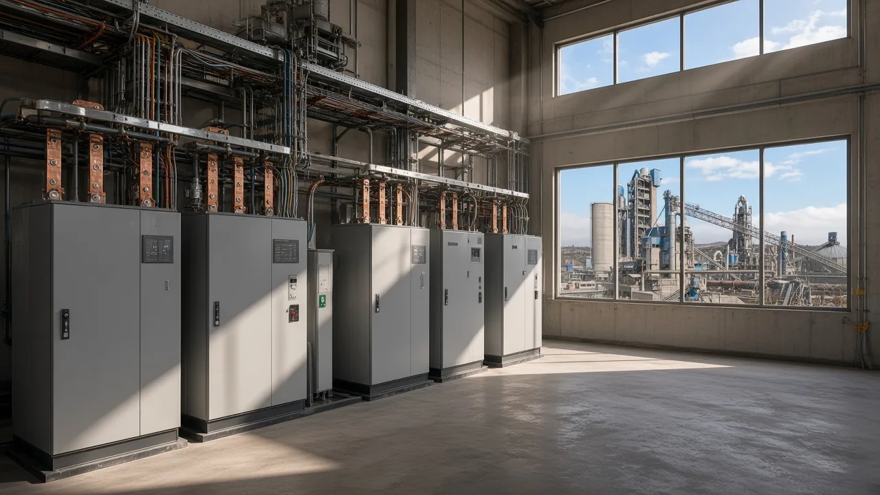
How crushers, mills, and VFDs change that call
Changing motor and VFD duty is why a teaching rectifier is the wrong analog. Cement and mining sites run crushers, ball mills, kilns, conveyors, ventilation fans, pumps, and hoists. Large starts and shifting production raise reactive current and can sag voltage on long feeders.
Where VFDs and rectifier loads put significant harmonics on those buses, the site configuration calls for detuned or tuned filters alongside soft starters, capacitor banks, and faster var equipment. A laptop rectifier with a fixed RLC load does not stand in for a mill that starts, ramps, and idles.
Cement & Mining Power Quality Solutions is the plant path for that duty. It asks for a single-line, transformer and load data, power factor, and harmonic measurements. It does not offer a simulation file.
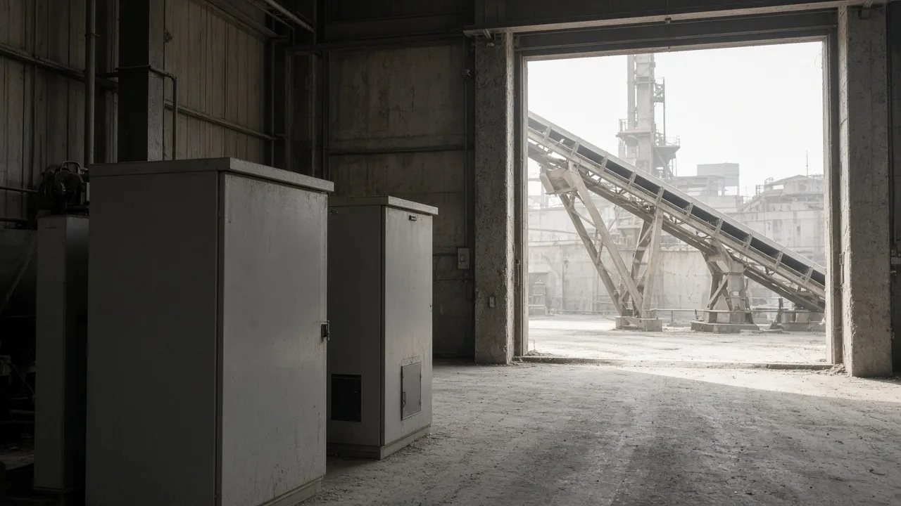
How to select HYAPF and a cement-mining solution fit
Select HYAPF for low-voltage opposite-current injection, and use the cement-mining solution as the plant path when the job has already left the laptop. HYAPF Series Active Power Filter measures load current in real time and injects an equal, opposite harmonic current into low-voltage distribution networks.
HYAPF Series Active Power Filter is published at 400 V or 690 V, covers orders from the 2nd through the 51st, responds in under 10 ms, and lists control accuracy as THD under 5%. Modules can be paralleled. The same frame can support reactive-power or load-imbalance compensation around nonlinear industrial and commercial loads, inside that current budget.
Open that product page when the specified current is an LV harmonic-injection job. Stay on the cement-mining solution when crushers, mills, and VFD harmonics define the site, and bring harmonic measurements rather than a scope screenshot. If the work is still a controller exercise, keep the teaching file and do not shop a cabinet.

FAQ
How do I extract id and iq in an SRF Simulink SAPF?
After the load current is in the dq frame, a low-pass filter near fundamental frequency keeps the DC piece. Subtract that piece from the total and the leftover is the harmonic reference you inverse-transform. That step lives on the canvas.
Is a File Exchange THD the current rating to buy?
No. A paper or listing FFT describes that model. The ampere rating comes from harmonic current on the plant load cycle.
Does CHYN sell a MATLAB/Simulink model?
No. CHYN sells injection hardware. The HYAPF page and the cement-mining solution do not publish a downloadable plant model.
Does a shunt APF model also study reactive and unbalance?
Yes on the canvas. p-q teaching files compensate imaginary power and can balance phases. That study still does not size a cabinet.
When does the job leave Simulink for plant hardware?
When opposing harmonic current has to enter the point of common coupling on a real nonlinear load. Until then, the file is the right tool.
What four blocks is the .slx analogizing?
Controller, voltage source inverter, DC-link capacitor, and coupling inductor. The drawing is an analog of those blocks, not a wiring diagram for a named job.
Why can vars work in the capstone model while harmonics fail?
Reactive and unbalance references can track a fundamental frame while 5th and 7th orders need the right sequence. A clean var trace does not prove harmonic injection is working.
Is the cement-mining page a Simulink download?
No. It is a plant configuration for crushers, mills, conveyors, fans, pumps, and VFD or rectifier harmonics, with measurement inputs rather than a model file.
References
- Wikipedia — Active power filter.
- Design and Simulation of Three Phase Shunt Active Power Filter Using SRF Theory.
- Modeling and Simulation of a PI Controlled Shunt Active Power Filter Based on P-Q Theory.
- Simulation Results of a Shunt Active Power Filter with Control Based on p-q Theory.
- Electronics Stack Exchange — Building a shunt active power filter in the synchronous reference frame.