
 Zhejiang Hongyan Electric Co., Ltd.
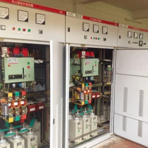
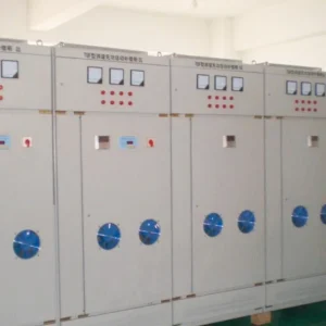
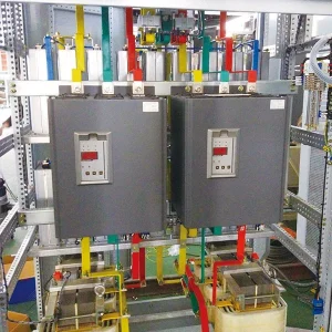
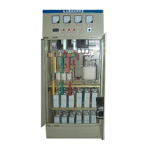
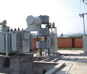
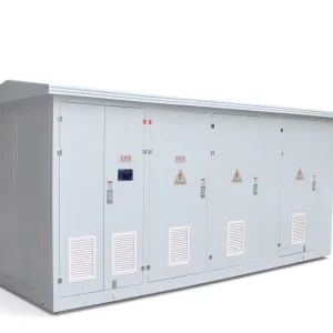
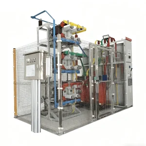
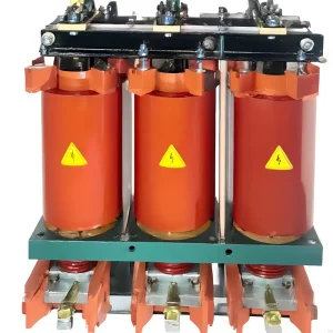
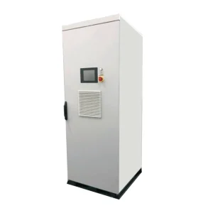
A dynamic voltage restorer acceptance test should prove that the agreed load continues operating through the specified supply disturbances and returns to normal service correctly. A healthy cabinet indication or a single corrected-voltage screenshot is insufficient evidence. Define the protected boundary, disturbance cases, measuring points and process pass criteria before testing. Record supply voltage, load voltage and load behavior on a common time base. Then compare every result with the approved purchase specification and the installed configuration. This approach connects electrical performance with the production outcome that justified purchasing the DVR.
Start with the protected load and the acceptance boundary
List exactly what the DVR protects: the complete machine, a distribution bus, selected drives or only a control supply. Mark the input and output terminals on the approved single-line drawing. Include auxiliary supplies, contactors and permissive circuits that can stop production even when the main power circuit rides through. A recorder connected to the wrong bus can make an apparently successful test irrelevant to the actual process.
Agree what continued operation means. For one application it might mean no controller reset and no dropped contactor. For another, it may require stable drive operation and an acceptable finished product. State which temporary deviations are permitted, who observes them and where they are recorded. Do not replace the process owner's acceptance criteria with a generic statement that the voltage looked normal.
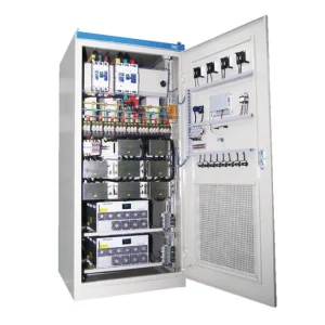
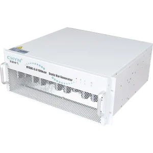
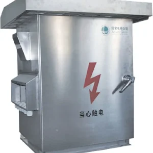
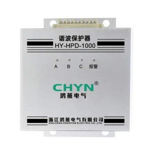
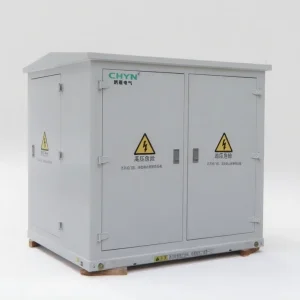
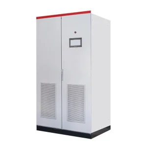
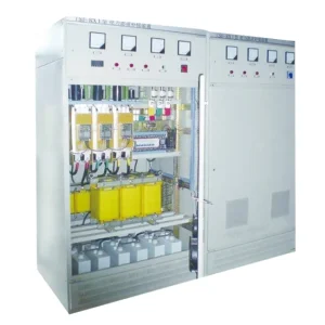
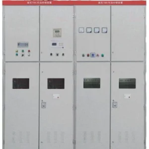
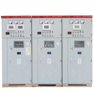
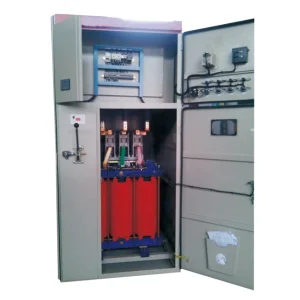
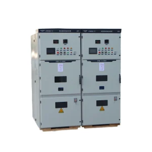
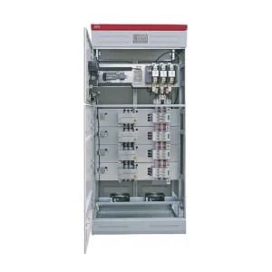
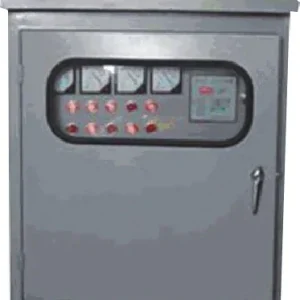
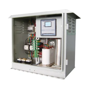
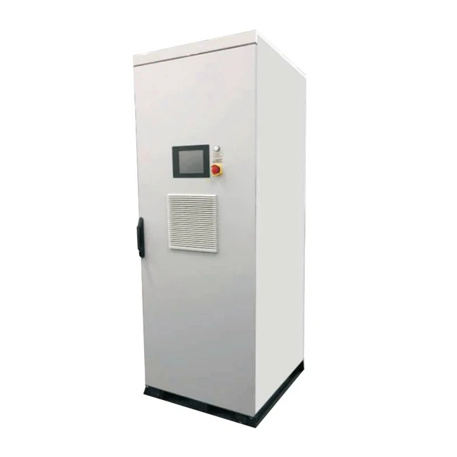
The CHYN HYDVR voltage sag mitigation product page provides a starting point for configuration discussions. Confirm the ordered voltage, load duty, energy arrangement and access requirements against approved documents. The cabinet photograph identifies the product family; it is not evidence that a particular supplied unit has passed these tests.
Build a disturbance matrix from the actual requirement
Each test case needs a defined residual supply voltage, duration, affected phases, load condition and starting state. Clarify whether a percentage refers to remaining voltage or voltage reduction. Record the voltage base and whether measurements are phase-to-neutral or phase-to-phase. This avoids two teams using the same percentage to describe different disturbances.
Include the event types relevant to the site survey and purchase agreement. Balanced sags alone may not represent single-phase faults or unbalanced events. Where phase-angle behavior matters, identify it explicitly instead of assuming equal RMS readings describe identical waveforms. Include recovery to normal supply and the required readiness for a subsequent event. Our voltage sag ride-through specification guide explains how to define the input envelope before selecting a solution.
Standards also require a scope check. The public description of IEC 61000-4-11 covers immunity testing for equipment rated up to 16 A per phase. IEC 61000-4-34 addresses equipment above 16 A per phase. Neither public catalogue description supplies an automatic acceptance certificate for an installed DVR. The responsible engineer must select the applicable edition, product requirements and contractual test conditions.
Prepare measurements that can explain a failure
Use suitably rated instruments and a qualified test team working under the approved electrical safety procedure. Establish recording channels for incoming voltage, protected voltage and relevant load current. Add the process status signals needed to identify a reset, trip or loss of production. Confirm channel labels, voltage references and time alignment before applying a disturbance.
Choose recording resolution and triggering that can capture the event features being assessed. A long averaging interval can hide a short interruption. A photograph of the display may omit the recovery transient. Retain raw waveforms and instrument settings alongside summary measurements so a later reviewer can understand how the reported values were produced.
Separate equipment response from instrument delay. If a contract specifies response time, define the start and finish markers and the measurement method in advance. Do not compare a controller event timestamp with an unrelated recorder clock and treat their difference as an accurate response measurement. Calibrated equipment and documented uncertainty are particularly useful when results sit near an agreed limit.
Use staged testing with clear stop conditions
Begin with document review, installation checks and control checks that do not require an imposed power disturbance. Verify the approved settings, alarms, interlocks and normal operating state. Confirm that the test source and connected load are compatible with the intended procedure. Stop if drawing discrepancies, unexplained alarms or unsafe isolation arrangements remain unresolved.
Move to controlled tests only within a qualified facility or an engineered site procedure. Creating a network fault is not a practical substitute for a suitable disturbance generator. Any intentional disturbance needs a reviewed method that protects personnel, neighboring equipment and the installation. Where site injection is impractical, distinguish factory evidence from the limited functions that can be demonstrated on site.
Increase test duty in the agreed sequence. Start with a representative operating condition, review the recordings and proceed only when the result is understood. Include the defined worst operating cases rather than assuming the highest kVA is always the most sensitive process state. A lightly loaded machine with an auxiliary contactor can fail differently from the same machine at full production.
Record evidence against each acceptance question
The following is a proposed project evidence checklist, not a table of standard limits. Populate the pass criteria from the approved contract, applicable standards and manufacturer instructions before testing.
| Acceptance question | Evidence to retain | Decision required |
|---|---|---|
| Was the specified disturbance applied? | Input waveform, residual voltage, duration and phase identification | Accept the case only when the applied event matches the approved matrix |
| Was the protected voltage acceptable? | Output waveform on the same time base as the input | Compare the agreed voltage and transient criteria |
| Did the load continue its task? | Drive, controller, contactor and process records | Confirm electrical continuity and the named production outcome |
| Did normal service recover correctly? | Recovery trace, alarms, operating state and recharge indication | Verify the approved return sequence and readiness conditions |
| Can the result be reproduced? | Configuration revision, instrument setup and test identifiers | Identify changes that require a repeat test |
Interpret a worked acceptance case carefully
Consider an illustrative 400 V installation whose approved test plan specifies 70% residual supply voltage for 200 ms under a named operating load. The residual RMS voltage for that case is 0.70 × 400 = 280 V on the same voltage basis. The amplitude difference is 120 V, but that arithmetic alone does not define injected voltage under every phase-angle or unbalanced condition. It also does not calculate the required stored energy.
The test team first confirms that the input trace matches the 280 V, 200 ms case. It then checks the protected-voltage record against the project's separate output criteria and compares controller and process logs. If the main bus recovers but an auxiliary supply drops a permissive, the installation has not demonstrated the agreed process continuity. Label this example as a planning illustration; it is not a CHYN rating or a universal test level.
If the event is passed once but the next specified event fails, investigate the initial state, thermal duty and energy recovery before assigning a cause. The companion article on DVR energy storage sizing covers the energy question separately. Acceptance testing should verify the agreed duty without silently expanding it beyond the purchased configuration.
Close out protection, exceptions and handover
Check that abnormal-state tests stay within the reviewed scope. Protection and bypass functions require their own approved sequence and coordination evidence; they should not be improvised during a voltage-performance demonstration. Refer to DVR bypass protection coordination when defining which fault-path checks belong in the project.
For every exception, record the test case, observed behavior, suspected cause and responsible action. Retesting should identify the exact settings or hardware revision used. Keep the original failed record as well as the successful repeat. Otherwise a handover pack can show a pass without explaining which configuration actually achieved it.
The final package should connect the purchase requirement, approved drawings, test matrix, instrument records, raw traces, process observations and signed disposition. Record functions that were not tested and the reason. If only factory testing was possible, describe the remaining site demonstration separately. A clear boundary around demonstrated performance is more useful than an unsupported claim of complete immunity.
Educational background: mitigating sags and interruptions
The lecture below explains voltage-sag mitigation principles. It provides context for understanding the input and protected-voltage traces; it does not replace a model-specific acceptance procedure or demonstrate the performance of a CHYN installation.
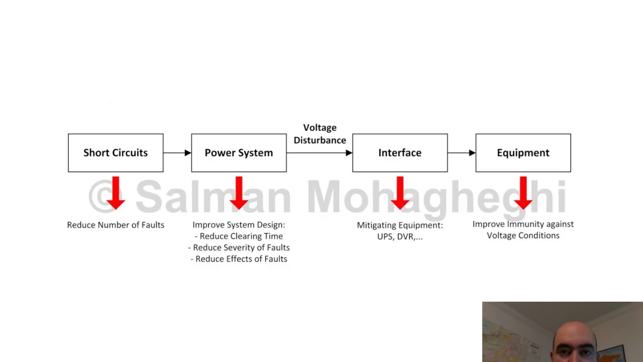
Watch the educational lecture on YouTube.
Frequently asked questions
Is an output-voltage screenshot enough to accept a DVR?
No. Retain the applied input event, protected output and relevant load or process records. A screenshot alone cannot establish the disturbance conditions or prove uninterrupted operation.
Should every DVR use the same sag test levels?
No. Select the levels, durations, phase conditions and load states from the applicable requirements and approved contract. Confirm the scope of any cited test standard.
Can factory testing replace every site check?
Factory evidence can demonstrate defined equipment functions. Site checks still need to address installation, settings, auxiliary supplies and the actual protected-load boundary within an approved safe procedure.
What should happen after a failed acceptance case?
Preserve the original record, identify the cause, document the change and repeat the affected cases. Do not remove the failure history or expand a limited retest into an unsupported overall pass.