
 Zhejiang Hongyan Electric Co., Ltd.
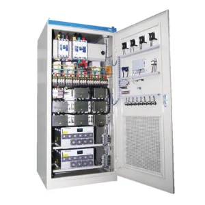
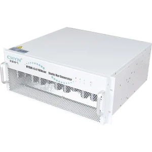
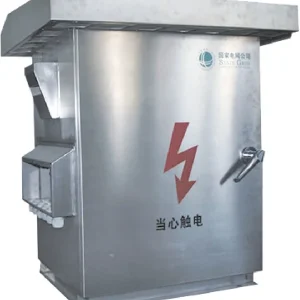
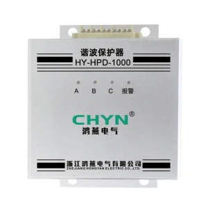
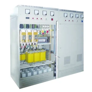
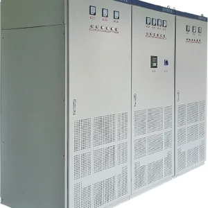
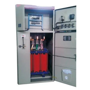
Dynamic voltage restorer energy storage sizing starts with the real power that must be injected during a defined voltage sag, multiplied by the required support duration. The result must then be checked against usable storage energy, discharge power, converter limits and recovery between events. A protected-load kVA value alone cannot establish the storage requirement. For an industrial purchase, ask for a support envelope tied to measured sag depth, duration, phase conditions and load behavior. The calculation below explains a screening method; it does not declare a storage capacity or ride-through guarantee for any CHYN configuration.
Identify where the compensating energy comes from
A DVR inserts a controlled voltage in series with the protected feeder. How its converter obtains the active power needed during a sag depends on the topology. An external storage device, a DC-link capacitor and an arrangement drawing energy from the remaining AC supply are different designs. Do not assume that every product called a DVR contains a battery, or that the visible cabinet reveals its internal energy source.
Aalborg University’s comparison of DVR system topologies examines both stored-energy and supply-fed arrangements. Its useful purchasing lesson is that the energy path must be identified before a duration claim can be interpreted. Request the actual arrangement offered for the project, including any separate storage cabinet and dependencies on residual supply voltage.
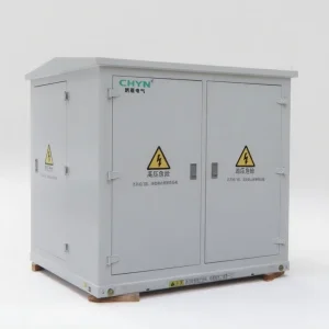
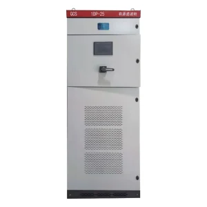
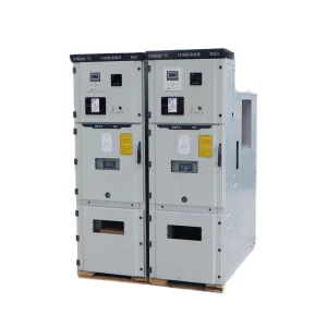
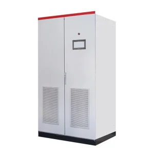
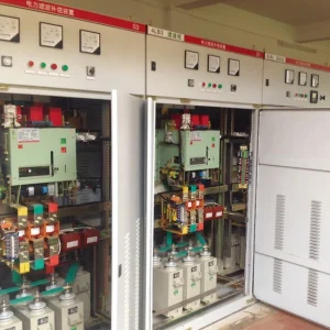
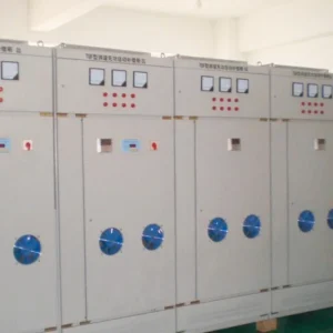
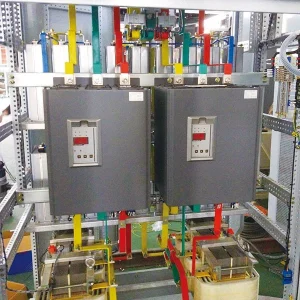
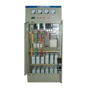
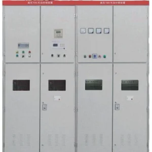
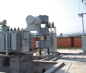
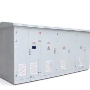
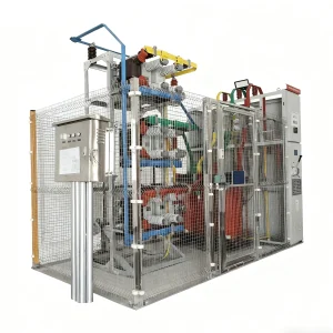
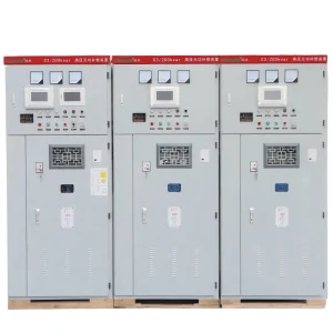
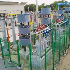
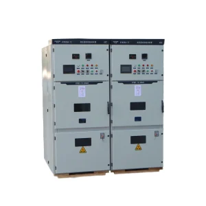
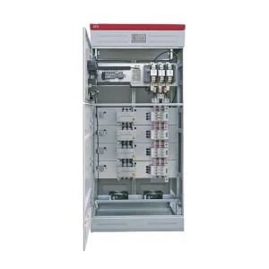
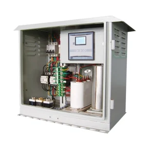
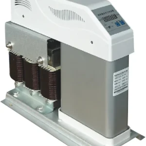
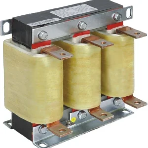
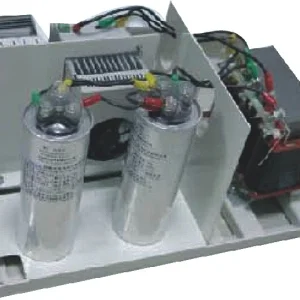
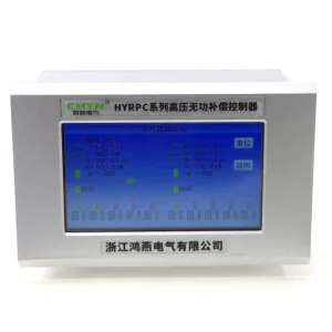
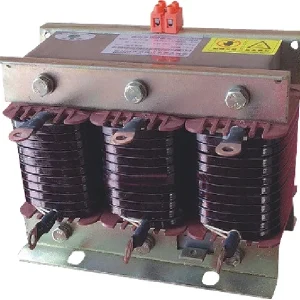
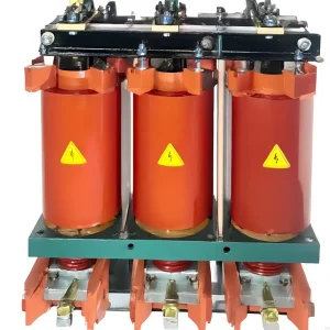
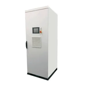
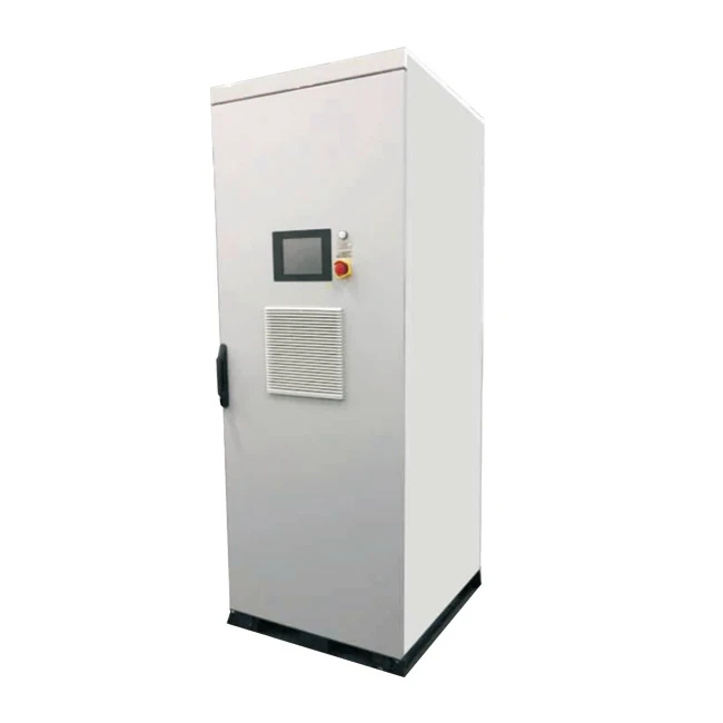
The CHYN HYDVR product page provides the relevant product starting point. Confirm the offered configuration with the supplier. An external photograph is a product reference, not evidence of installed storage capacity, usable energy or a particular compensation mode.
Build an event description before calculating joules
Collect synchronized voltage and current records from the feeder being protected. The description should include residual voltage on each phase, event duration, phase-angle changes, load current and whether the process continues drawing approximately constant power. Preserve the recorder settings and measurement location. A percentage recorded elsewhere on the distribution system may not describe the voltage seen at this load.
Separate the process requirement from the recorder event. A machine may tolerate part of the disturbance, or it may need an uninterrupted control supply even when the main motor can coast. List which loads the DVR actually protects. Including unrelated feeder loads can inflate the request; omitting control or auxiliary loads can leave the process vulnerable despite a satisfactory main-power calculation.
For a broader event specification, use the voltage sag ride-through specification guide. Here the narrower objective is to turn an agreed disturbance into an energy and recovery review, without repeating the complete equipment selection process.
Use a transparent first-pass energy calculation
For a balanced, sinusoidal sag with no phase jump, assume the DVR restores nominal load voltage by injecting voltage in phase with the original supply. Let r be residual supply voltage in per unit of nominal, Pload the total three-phase load active power in kW during support, and t the event duration in seconds. Under these simplifying assumptions, Pinj ≈ (1 − r) × Pload, and EAC ≈ Pinj × t.
The result is in kJ because one kW sustained for one second equals one kJ. This is delivered active energy, not the converter apparent-power rating. A converter must also meet its voltage and current obligations. The screening expression is inappropriate for an unbalanced event, changing load, material phase jump or different injection strategy without a more complete phase-by-phase assessment.
Consider a hypothetical protected load drawing 200 kW throughout a balanced event, with residual voltage r = 0.60 for 0.40 seconds. The simplified injected active power is 80 kW and the delivered energy is 32 kJ. If an assumed discharge-path efficiency of 0.90 applied, the corresponding storage withdrawal would be approximately 35.6 kJ. These are invented teaching inputs, not CHYN performance data or a recommended engineering margin.
The efficiency assumption does not include every possible auxiliary demand or operating restriction. Nor does 35.6 kJ become a purchase capacity automatically. Ask the supplier to replace assumptions with configuration-specific evidence and to identify how much stored energy remains unavailable below the permitted DC voltage or other operating limit.
Distinguish nominal storage from usable storage
A capacitor’s stored energy follows E = ½CV². For a capacitor-supported DC link, the ideal energy released between two permitted voltages is ½C(Vhigh² − Vlow²), with C in farads, voltage in volts and energy in joules. OpenStax explains the capacitor energy relationship. Applying it to a DVR still requires the supplier’s actual DC operating boundaries.
For example, an ideal 0.10 F equivalent capacitance falling from 800 V to 600 V releases 14 kJ. The arithmetic is 0.5 × 0.10 × (800² − 600²). It cannot establish that a real DVR operates across that voltage range. Cell balancing, tolerances, temperature, current limits and conversion behavior may narrow the usable window. Do not use this example as a construction or component replacement instruction.
With battery or other storage, request both usable energy and discharge-power capability at the specified condition. A large energy inventory can still fail a short, high-power duty if its power path is inadequate. Keep the requested end-of-life condition and site environment explicit, and obtain the supplier’s documented treatment rather than applying an unexplained universal percentage.
| Review item | Information to request | Decision it supports |
|---|---|---|
| Delivered active energy | Time-integrated injection power for each agreed event | Whether the support demand fits the usable energy budget |
| Instantaneous power | Discharge power and converter current limits | Whether energy can be delivered quickly enough |
| Storage window | Permitted operating limits and readiness conditions | How nominal storage translates into usable support |
| Repeated events | Minimum recovery interval for a stated sequence | Whether a second event remains within the support envelope |
| Configuration evidence | Test records tied to offered hardware and settings | Whether the quoted duration applies to the purchased system |
This is a purchasing decision table, not a set of standard limits. The energy relationships above and the topology reference explain why these questions are separate.
Review the second event, not only the first
Ask what happens after support ends. A unit may restore its normal voltage output before its energy reserve has returned to the declared ready condition. Require the meaning of “ready” to be stated. A screen showing normal feeder voltage does not by itself prove the reserve can support another full event immediately.
Define a repeat-event sequence using the site’s disturbance history or agreed design scenario. Specify the interval, load and residual voltage for each event. Request the supported duration for the second and subsequent events, together with recharge limitations. If recovery depends on supply quality or load state, that dependency belongs in the quotation and operating instructions.
Also review recovery demand on the feeder. The project engineer should assess the charging arrangement with the site supply and other equipment. Do not infer a recharge current from the simple sag-energy example: charging losses, limits and control settings may differ from the discharge path.
Ask for an operating envelope and a repeatable demonstration
Present the supplier with an event matrix rather than a single duration. Include the protected load, minimum residual voltage, required duration and permitted load-side result for each row. Add phase conditions and repeated events where relevant. Request a written statement of supported and unsupported combinations, with the normal starting condition identified.
For acceptance, agree how load voltage, current and energy-source condition will be recorded through initiation, support, clearance and recharge. Testing must use an approved facility and qualified personnel. The purpose is to verify the declared configuration safely, not to create uncontrolled disturbances in a working plant.
Use the separate DVR phase-angle jump guide when phase continuity affects injection demand. For a decision involving prolonged loss of supply, review the DVR versus UPS comparison. Neither a capacitor energy formula nor a short sag test establishes full interruption backup.
Further learning: voltage-sag mitigation
The following educational lecture by Salman Mohagheghi’s power-quality teaching channel discusses sag and interruption mitigation. It provides context for the compensation problem; the numerical screening examples and purchasing checklist above remain self-contained. Confirm actual storage design and acceptance conditions with the equipment supplier.
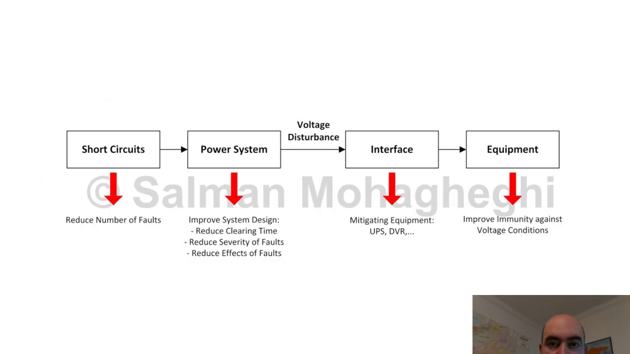
Watch L19 Mitigating Sags and Interruptions on YouTube.
Frequently asked questions
Does a DVR kVA rating tell me how many seconds it can support a load?
No. The converter must meet voltage and current duties, while sustained active-power injection also needs an adequate energy path. Ask for the supported sag-depth and duration envelope at the actual load. A single apparent-power figure cannot establish usable energy, recovery time or performance during repeated events.
Can I size storage using the missing voltage percentage alone?
No. You also need load active power, duration and the compensation conditions. The simple expression in this guide assumes a balanced sag without a phase jump and a defined load power. Unbalanced or changing events need a more complete assessment of each phase and the chosen control strategy.
Is all energy stored in a DC-link capacitor usable?
No. The converter generally has a permitted operating window. Only the energy between the accepted upper and lower DC limits can enter an ideal usable-energy calculation, before accounting for other restrictions and losses. Obtain those limits for the supplied configuration rather than choosing them from this teaching example.
What should I ask about consecutive voltage sags?
Specify the required sequence, interval and load, then ask for the support available at each event. Require a clear definition of readiness and the recharge conditions. Normal feeder voltage after the first event does not, by itself, establish that the reserve has returned to its full accepted condition.