
 Zhejiang Hongyan Electric Co., Ltd.
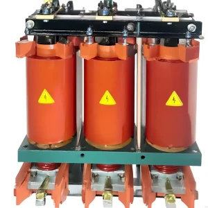
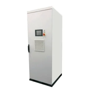
Choosing a dynamic voltage restorer vs UPS depends on what the load must survive. A DVR is commonly specified to correct voltage sags by injecting a compensating series voltage within a defined operating envelope. A UPS is specified to maintain power continuity using stored energy when its input supply is unacceptable or absent, within its ratings and runtime. A short sag, a complete interruption, and a long outage are different design duties. Compare the measured event, protected load boundary, energy requirement, bypass behavior, and acceptance test before comparing cabinet size or purchase price.
Start with the event and the required process outcome
A sag leaves some supply voltage available. An interruption can leave the load with effectively no usable supply. The depth, duration, affected phases, phase-angle behavior, and recovery all influence what protection is needed. A product that handles one documented sag is not automatically suitable for a longer or deeper event.
Define the desired outcome as well. The facility may need a controller to remain running, an entire production line to continue, or a process to shut down in a controlled way. Those objectives require different protected loads and different energy reserves. Keeping the PLC alive is not sufficient if an unsupported drive, contactor, remote I/O supply, or network device stops the process.
If the cause of the stoppage has not been established, begin with the PLC voltage-sag troubleshooting guide. This comparison assumes the vulnerable loads and disturbance profile have been identified; its purpose is to help specify the protection system rather than repeat the diagnostic procedure.
What a DVR does, and where its limits matter
A dynamic voltage restorer uses a power-electronic system to add a controlled series voltage so the protected load receives a suitable voltage during the specified disturbance. The implementation can differ in energy source, storage, injection strategy, coupling, bypass, and supported phase conditions. The label DVR does not establish one universal depth-duration capability.
Some sag-correction arrangements use energy available from the remaining supply, while others include dedicated storage. Complete-interruption support therefore needs an explicit guarantee for the actual design. Do not assume either that every DVR is battery-free or that every DVR can sustain a load when the source disappears.
The supplier must define residual input voltage, event duration, affected phases, allowable phase-angle changes, protected load, repeated-event duty, and recovery conditions. Confirm what happens outside that envelope. A bypass or protective action can expose the load to a disturbance even though the equipment remains electrically intact.
LADWP's power-quality guidance identifies both UPS support and dynamic sag correction as possible responses to supply disturbances. The choice still depends on the source of the problem and the equipment's required ride-through capability.
What a UPS adds to the specification
A UPS combines power conversion, switching, and an energy-storage arrangement to preserve continuity of supply to its protected load. The U.S. Department of Energy UPS description identifies continuity during input-power failure as its purpose. Actual runtime and output behavior depend on the selected topology, load, storage condition, and operating mode.
Do not treat every UPS as an identical ideal voltage source. Confirm its normal operating mode, transitions, output quality, overload behavior, available fault current, and response to the particular load. A system suitable for a defined electronic load cannot be assumed suitable for a large motor, regenerative drive, or a production line with substantial starting demand.
Storage needs its own lifecycle plan. Capacity, state of charge, temperature, aging, recharge time, and repeated discharge duty can affect the available runtime. The quotation should state the load and end-of-life assumptions supporting the promised autonomy, not just an unloaded or new-storage runtime.
IEC 62040-3 provides methods for specifying UPS performance and test requirements within its stated scope. Request the applicable classification and supporting test documentation. A reference to that standard is not evidence that a particular UPS has already passed the acceptance conditions of the project.
DVR and UPS comparison by design duty
| Project question | DVR selection emphasis | UPS selection emphasis |
|---|---|---|
| What event must be covered? | Specified sag depth, duration, phase pattern, and any separately guaranteed interruption capability. | Input failure or unacceptable input, with specified output continuity and autonomy. |
| What sets the energy requirement? | Missing voltage and required injection duty, together with the design's energy source. | The protected load's power and required stored-energy operating time. |
| What current must the equipment accommodate? | The full series load current and applicable overload and fault duties. | The rated output load, transients, overloads, and required fault behavior. |
| What must be checked during bypass? | Whether the protected load receives uncorrected supply and how faults are cleared. | Whether stored-energy protection remains available in the stated bypass condition. |
| What proves suitability? | A guaranteed event envelope plus a process-level acceptance test. | A guaranteed load/runtime envelope plus output and transition tests. |
This table is a procurement framework, not a claim that a DVR is always preferable for industrial loads or that a UPS is always preferable for electronics. The actual load and disturbance determine the engineering requirements.
Compare energy and power without confusing the ratings
Consider a simplified balanced case in which an in-phase sag reduces voltage to 70% of nominal while the load must maintain its normal voltage and active power. The missing voltage is 30%. In an ideal in-phase series-injection model, the DVR's active injection power is approximately 30% of load active power. Real designs also require analysis of reactive power, phase-angle behavior, conversion losses, and available source current.
For an illustrative 300 kW load and a 0.2-second event, the ideal missing active energy is 0.30 × 300 kW × 0.2 s = 18 kJ, or 0.005 kWh. By comparison, supporting that complete 300 kW load for a five-minute outage requires 300 × 5/60 = 25 kWh at the load before losses and reserve. These are different protection objectives, not two guaranteed solutions to the same event.
A small energy figure does not imply a small current requirement. At 400 V, a balanced 300 kW load with power factor 0.9 has an apparent power of approximately 333 kVA and line current of 333,000 / (√3 × 400) ≈ 481 A. Series equipment and its bypass still need to accommodate the applicable load current. An injection-power calculation cannot be substituted for the manufacturer's complete DVR rating convention.
Similarly, a UPS selected from kilowatt-hours alone may fail a load transient or overload requirement. Evaluate power, apparent power, current, energy, and time separately. State the assumptions behind every number so suppliers do not quote against different interpretations of the same enquiry.
Decide which loads belong inside the protected boundary
For a controls-only requirement, list every component needed to preserve the intended control state. That may include remote supplies, communications equipment, safety-related interfaces, and process instrumentation. For a whole-machine requirement, include drives, contactors, auxiliaries, and any other component whose loss interrupts production.
A wider boundary increases protected load, possible inrush, maintenance implications, and interaction with upstream and downstream protection. A narrower boundary can reduce equipment size but leave a weak link unprotected. Trace the complete operating sequence rather than protecting only the cabinet with the most visible display.
The manufacturing plant solution overview provides wider application context. The final specification should identify precisely which feeders and devices receive corrected or backed-up power, and which supply conditions remain outside the project.
Check bypass, fault clearing, and recovery before purchase
Normal operation is only one state of the system. Ask for behavior during overload, downstream faults, internal faults, loss of control supply, depleted storage where applicable, and scheduled maintenance. Identify the conditions that cause transfer to bypass, output interruption, or a controlled shutdown.
Review the available fault current and protective-device coordination in every relevant operating mode. A downstream protective device that operates as intended on the normal supply may behave differently on a current-limited converter source. The responsible designer should verify selectivity, clearing, earthing, and the load's safe response using the actual system data.
Recovery matters too. Ask whether output restoration creates a voltage step, phase-angle change, transfer event, or inrush demand that affects the process. Specify what must happen after repeated disturbances and how the system reports reduced availability during recharge or recovery.
Where CHYN's HYDVR fits the enquiry
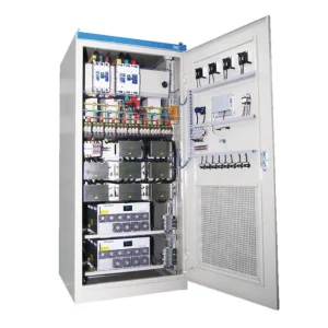
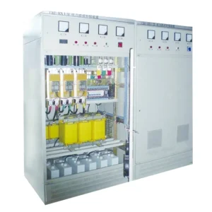
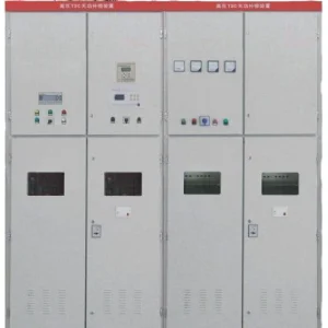
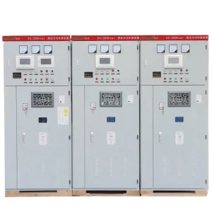
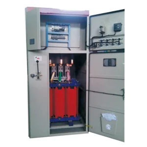
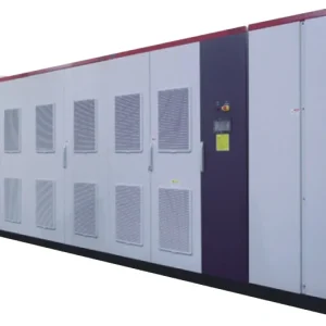
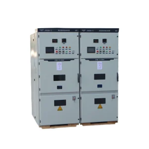
The CHYN HYDVR voltage-sag mitigation product family is relevant when the duty calls for a documented sag-correction envelope. Submit the measured events, protected load, supply conditions, and required process result. Obtain the proposed model's injection, current, energy, bypass, and protection details in writing.
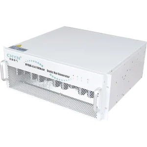
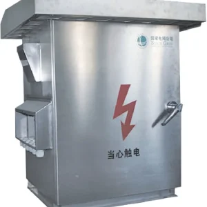
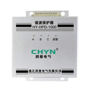
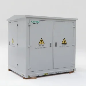
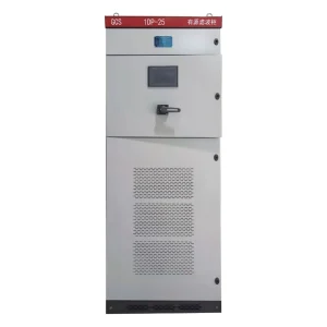
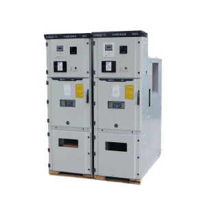
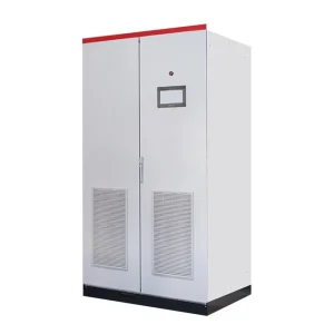
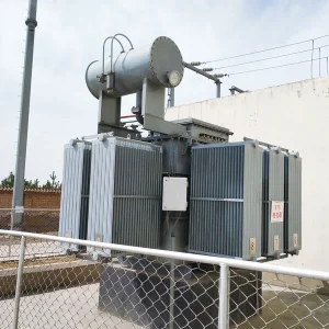
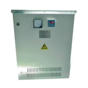
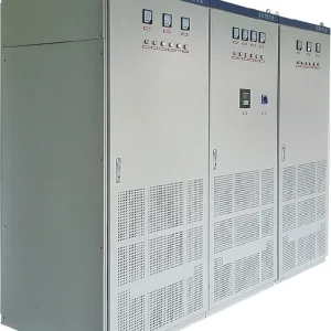
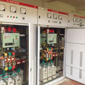
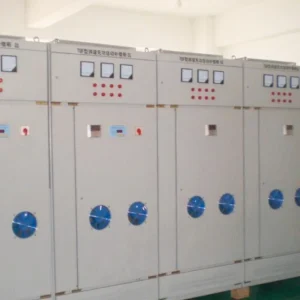
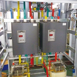
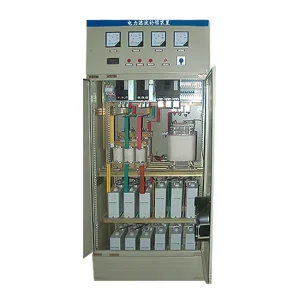
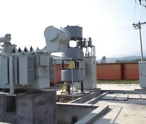
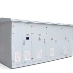
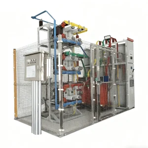
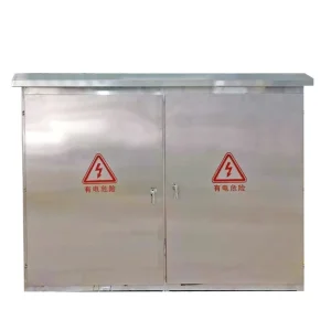
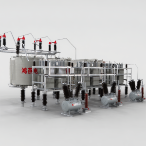
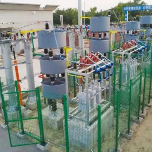
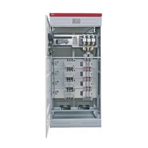
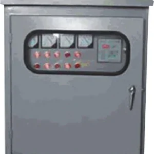
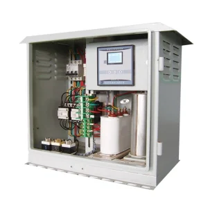
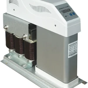
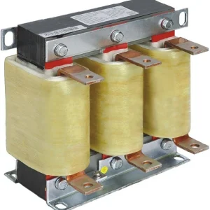
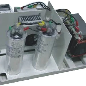
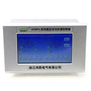
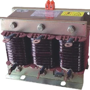
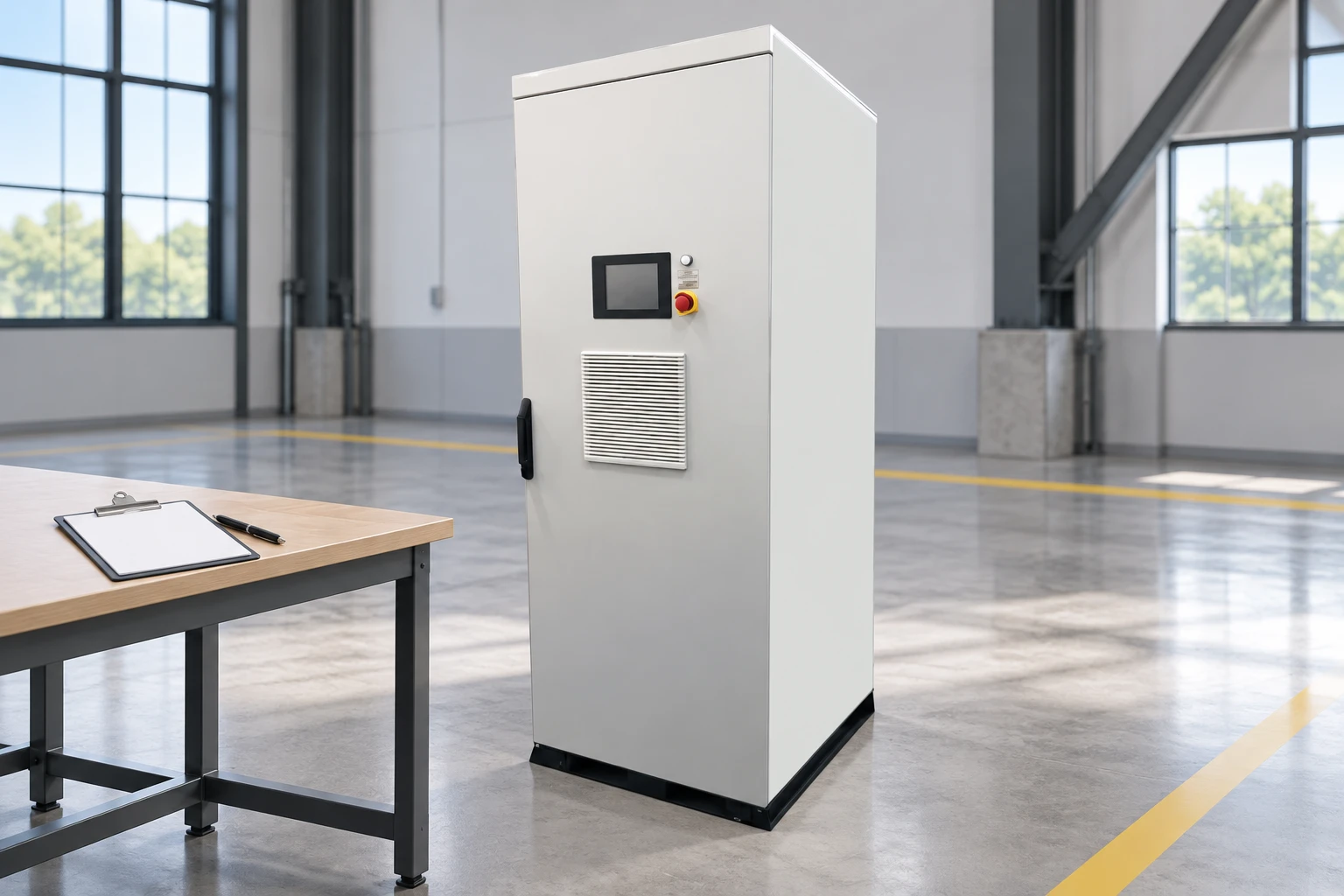
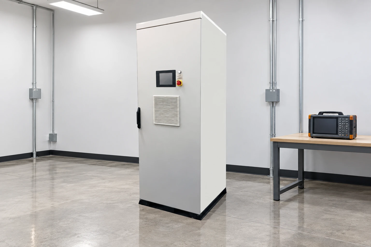
The illustrations use the existing HYDVR cabinet photograph to show product context. They do not depict a UPS, an installed comparison test, or proof of interruption runtime. If sustained outage autonomy is required, make that requirement explicit and obtain a UPS or other continuity-system proposal that actually covers it.
Reactive-power and harmonic-current equipment address different duties. The SVG versus active harmonic filter comparison explains those choices, while the power-quality causes guide helps place supply events in the broader plant investigation. Do not treat one category as an automatic substitute for another.
RFQ and acceptance checklist
- Provide the one-line diagram, supply voltage and frequency, earthing arrangement, alternative supply modes, and protected feeders.
- Attach event recordings with residual voltage, duration, phases affected, recovery, and the corresponding process failures.
- State load kW, kVA, power factor, starting and transient demand, nonlinear characteristics, and any regenerative behavior.
- Separate sag ride-through time from complete-interruption and long-outage autonomy.
- Request a guaranteed operating envelope, storage assumptions where relevant, bypass behavior, fault-coordination information, and maintenance requirements.
- Agree before-and-after recordings and a process-level test that demonstrates the intended continuity or controlled shutdown.
A technically comparable quotation states what the load will receive during the required event and what happens beyond the guarantee. That is more useful than selecting a DVR or UPS from a generic claim of fast response, high efficiency, or uninterrupted operation.
Further learning: mitigating sags and interruptions
Electrical engineering educator Salman Mohagheghi's lecture below explains sag and interruption mitigation. It provides independent background for the comparison rather than a recommendation of any commercial DVR or UPS.
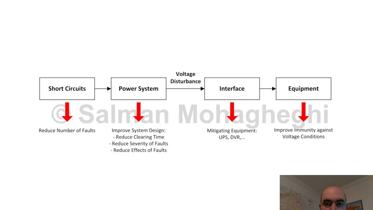
Watch L19 Mitigating Sags and Interruptions on YouTube.
Frequently asked questions
What is the main difference between a DVR and a UPS?
A DVR is commonly selected for series voltage correction during specified sags. A UPS is selected to preserve continuity using stored energy when the input supply is unacceptable or absent, within its ratings and runtime.
Can a DVR protect against a complete interruption?
Some designs can support specified interruptions, while others depend on remaining supply energy. Obtain an explicit guarantee for the proposed model, load, event depth, and duration.
Does a small sag-energy calculation mean the DVR can have a small current rating?
No. Series equipment and its bypass must accommodate the applicable full load current and fault duties. Injection power and stored energy are only parts of the selection.
Is a UPS for the PLC enough to keep a production line running?
Only if every component required for the intended process outcome remains adequately supplied. Drives, contactors, remote I/O, communications, and auxiliaries may need protection as well.