
 Zhejiang Hongyan Electric Co., Ltd.
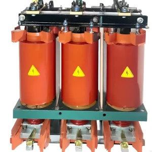
A dynamic voltage restorer phase angle jump specification must describe the load-voltage phase as well as its magnitude. Restoring the RMS voltage alone does not prove that a sensitive process will tolerate the event. Ask which compensation mode the selected DVR uses, how much series injection it can provide, and how it returns to normal supply. Keep sag depth, duration, phase displacement and load conditions together in the acceptance record. This guide explains the difference between magnitude restoration and phase restoration, with a simplified calculation and a practical procurement checklist.
Why the same RMS sag can require different compensation
A voltage waveform has a time reference. A sudden displacement of that reference during a disturbance is a phase angle jump. Two events can have the same remaining RMS voltage and duration while presenting different phase changes. An event report that retains only the lowest voltage therefore loses information relevant to a series compensator. The load may also respond differently at the beginning and end of an otherwise similar disturbance.
For procurement, separate three questions: whether the load receives sufficient voltage magnitude, whether its phase reference remains acceptable, and whether the process continues operating. Those are related outcomes, but one does not automatically establish the others. A voltage trace can meet its magnitude target while a controller loses synchronization or a contactor drops out for another reason. Define the required outcome with the process owner before requesting equipment.
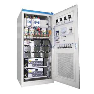
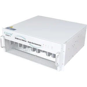
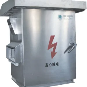
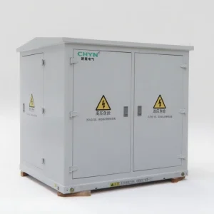
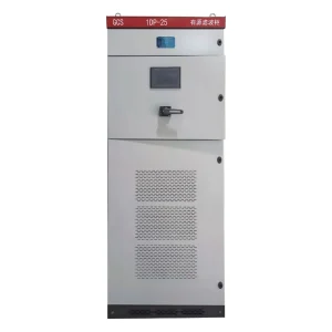
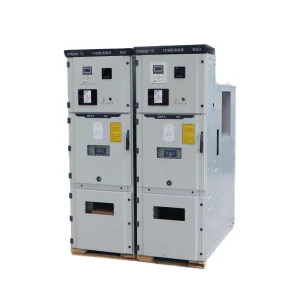
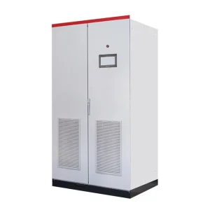
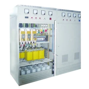
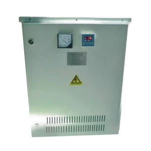
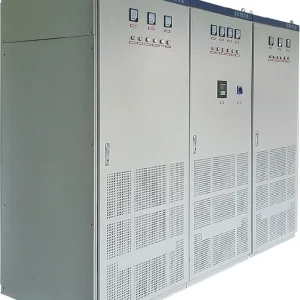
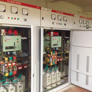
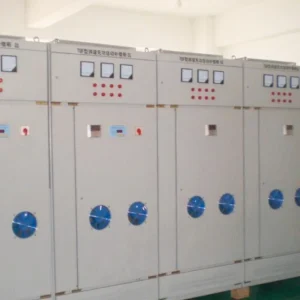
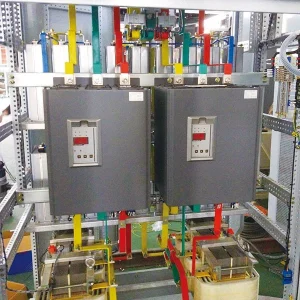
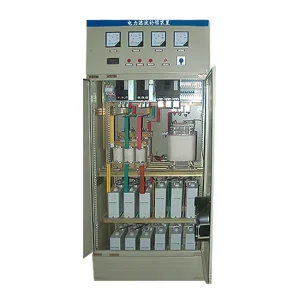
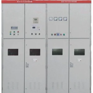
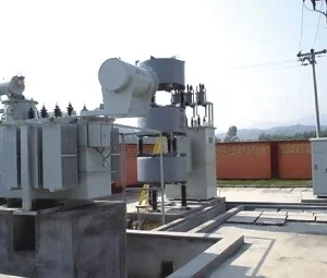
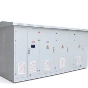
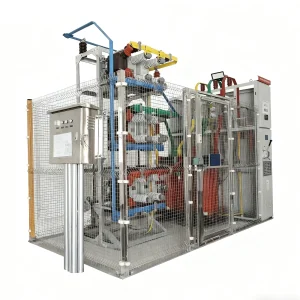
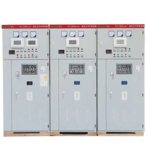
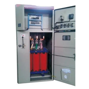
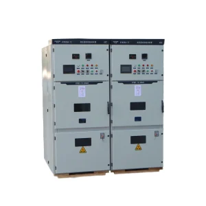
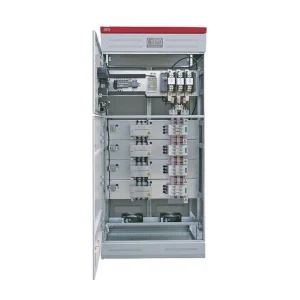
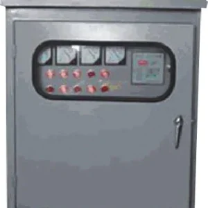
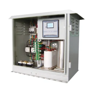
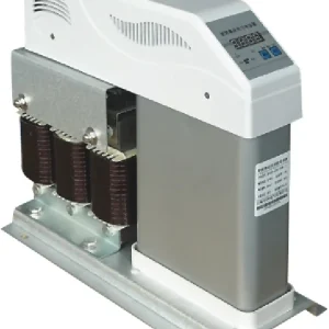
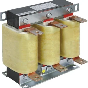
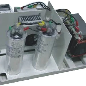
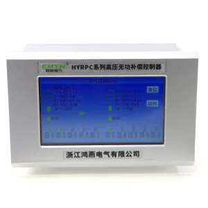
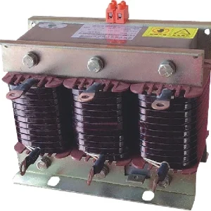
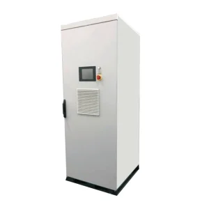
The CHYN HYDVR voltage sag mitigation product is the relevant product family for a project discussion. Its website photograph identifies the enclosure, not the approved phase-restoration capability of every configuration. Obtain the selected configuration's written operating envelope. Do not turn a family-level description into a promise that every disturbance will be corrected.
Compare compensation modes against the load requirement
In-phase compensation adds a voltage aligned with the sagged supply. It can restore magnitude while retaining the supply's displaced phase. Pre-sag compensation instead aims to reproduce the earlier voltage reference; its required injection is the vector difference between that reference and the remaining supply. Energy-oriented methods introduce another tradeoff between voltage quality and energy use. These distinctions are discussed in Aalborg University's research on DVR design and control.
Use those categories to frame questions, rather than assigning a preferred algorithm from a brochure. A process that tolerates a phase transition may accept a different solution from one requiring continuity of the earlier reference. Ask what happens when the requested injection exceeds the converter's available voltage or current. The answer should describe the actual limiting behavior and the resulting load voltage, not simply repeat the nominal output rating.
| Project requirement | Evidence to request | Common omission |
|---|---|---|
| Voltage magnitude restoration | Supply and load RMS traces with the same time reference | Reporting only the final steady voltage |
| Phase continuity | Defined pre-event reference and load-side phase displacement | Assuming nominal RMS voltage proves phase restoration |
| Support duration | Depth, phase change, load and initial storage condition together | Quoting a duration without its associated event |
| Recovery to supply | Waveforms through disturbance clearance and return to standby | Ending the test before the recovery transition |
| Repeated events | Permitted event spacing and readiness indication | Assuming immediate repeat support after a successful test |
This is an evidence checklist, not a universal performance standard. Acceptance limits must come from the load requirement and the approved equipment design. The broader voltage sag ride-through specification guide explains how to document the disturbance and process requirement before selecting a mitigation approach.
A phasor example: phase restoration can increase injection
Consider a deliberately simplified single-phase equivalent using fundamental RMS phasors. Let the desired load voltage be 1.00 per unit at the pre-event angle. Let the supply fall to 0.70 per unit and change its angle by 20 degrees. The requested series voltage for restoration to the pre-event reference is the vector subtraction of those two voltages.
Vinj = Vtarget − Vsag, and therefore |Vinj| = √(Vtarget² + Vsag² − 2VtargetVsagcos δ). Here the voltage magnitudes are RMS values on the same per-unit base, and δ is the angle between their references. For 1.00, 0.70 and 20 degrees, the result is approximately 0.418 per unit.
If the objective were only magnitude restoration aligned with the sagged supply, the illustrative voltage difference would be 1.00 − 0.70 = 0.30 per unit. That comparison shows why a statement such as “restores a 30 percent dip” cannot, by itself, establish phase-restoration capability. The 0.418 result is an illustrative demand, not an available rating of CHYN equipment or a recommended design margin.
This calculation ignores harmonics, phase-specific unbalance, transformer limitations, controller dynamics and load changes. It cannot determine storage size or certify a complete system. In a three-phase project, each required sequence and wiring arrangement needs its own assessment. Preserve the calculation assumptions so the supplier can identify where its application model differs from this simplified example.
Keep voltage limits separate from energy limits
Injection voltage, converter current and stored energy describe different restrictions. Sufficient energy does not remove a voltage ceiling. An adequate voltage ceiling does not establish how long the equipment can sustain the required real-power exchange. Load current and its phase relationship also matter. Ask the supplier to identify which restriction controls each requested event, including any transition from full correction to a limited operating mode.
Record the initial readiness condition for a test. Storage voltage or state, temperature, previous events and recharge status can affect the available response. Avoid combining the deepest sag from one test and the longest support time from another as though they describe a single verified capability. Retain complete event pairs and the operating conditions under which each result was obtained.
For deciding where a DVR fits in the site's continuity plan, use the DVR and UPS comparison. A phase-restoration requirement does not convert a series compensator into unlimited interruption support. Identify complete supply loss and bypass behavior separately, especially where the protected process depends on auxiliaries outside the selected feeder.
Test the start, the sustained interval and the return
A useful witness test captures the pre-event state, disturbance onset, supported interval, clearance and return to normal operation. Synchronize supply voltage, load voltage, load current and relevant process signals. A screenshot taken after recovery cannot explain a trip that occurred during the transition. Agree on recorder settings and the phase reference before interpreting the result.
Research indexed by the CPSS journal paper on DVR compensation and energy recovery explicitly considers phase-jump effects during recovery. For a purchasing team, the practical implication is to include clearance behavior in the test schedule. This is a project acceptance recommendation, not a claim that the cited research algorithm is installed in the offered product.
Use an agreed event matrix rather than improvising increasingly severe disturbances during commissioning. List balanced and relevant unbalanced cases, event duration, phase displacement, load level, permitted repetition and expected response. Include the process owner's pass condition and a safe stop condition for each test. Specialist personnel must design and execute disturbance testing within the approved installation and protection arrangements.
Build a quotation package the supplier can assess
Send the single-line diagram, feeder voltage, frequency, wiring arrangement and protected load inventory. Attach measured event waveforms where available. Identify whether the recorder measured phase-to-phase or phase-to-neutral voltage, how it calculated the phase change, and whether all channels share a reference. A table of event minima without those details may not be sufficient to reproduce the duty.
Describe the process consequence in concrete terms: restart required, synchronization lost, control alarm, rejected production or another documented outcome. State which loads are protected and which remain on the unconditioned supply. Ask for the proposed compensation strategy, voltage/current limits, support envelope, bypass sequence, recovery behavior and readiness indication in the same technical submission.
During technical review, challenge ambiguous language. “Fast response” needs a definition and test method. “Phase correction” needs a reference and allowed error. “Protection time” needs its depth, load and storage conditions. A clear submission lets the purchaser compare offers against one requirement instead of comparing unrelated headline ratings.
If a production line still trips while the monitored feeder voltage appears acceptable, use the PLC voltage sag troubleshooting guide to trace control-power and auxiliary behavior. Keep the protected electrical boundary aligned with the process being assessed.
Further learning: voltage sag mitigation
The following university lecture introduces mitigation of sags and interruptions. It provides background for the system discussion; it does not establish the phase-restoration limits of a particular product. Read the selected equipment documentation and agreed test plan alongside the lecture.
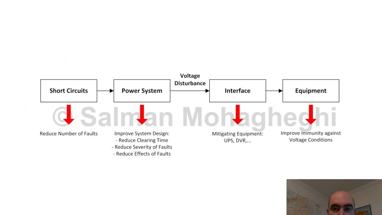
Watch L19 Mitigating Sags and Interruptions on YouTube.
Frequently asked questions
Does restored RMS voltage prove that a phase jump was corrected?
No. A compensator can restore the voltage magnitude while retaining a changed phase reference. State the required load-side phase behavior separately and request synchronized event records. The acceptance criterion should cover both the electrical output and the protected process response rather than relying on a final RMS display.
Can every DVR use pre-sag compensation for every event?
No. The selected strategy must operate within the configuration’s voltage, current and energy limits. Request a written envelope for the actual load and disturbance. A description of the compensation principle does not establish that every unit can reproduce the pre-event reference throughout every possible voltage sag.
Does the 0.418 per-unit example select a DVR rating?
No. It is a simplified fundamental-frequency vector calculation for one hypothetical event. It excludes control transients, unbalance and equipment constraints. Its purpose is to illustrate how a phase change alters injection demand; the supplier must assess the complete project and declare the applicable operating limits.
Why should testing continue after the voltage sag clears?
The return to normal supply is part of the disturbance response. Record load voltage, current and process status through clearance and recovery, using the agreed reference. A successful supported interval alone does not prove an acceptable return transition or immediate readiness for another event.