
 Zhejiang Hongyan Electric Co., Ltd.
A capacitor bank rated for 50 Hz cannot be approved for 60 Hz service from its kvar label alone. At unchanged capacitance and RMS voltage, an ideal unreactored capacitor produces 20 percent more reactive power at 60 Hz than at 50 Hz. That calculation predicts electrical demand; it does not grant operating permission. Check the capacitor's declared frequency and voltage ratings, then review the reactor, switching devices, protection, controller and complete assembly. This guide separates the calculation from the equipment approval and explains what to include in an export-project or replacement enquiry.
Start with the installed circuit and its actual ratings
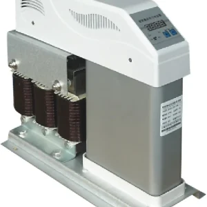
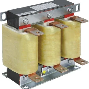
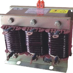
Identify whether the bank is a plain capacitor assembly, a detuned reactor-capacitor combination or another filtering arrangement. The simple frequency scaling discussed here applies to fixed capacitance without a series reactor. A reactor changes the branch impedance and the voltage across the capacitor. Treat a complete compensated branch as a designed combination rather than a collection of independently interchangeable parts.
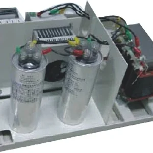
Collect the capacitor's capacitance, rated voltage, stated frequency and kvar basis. Record whether a nameplate describes an individual unit, one stage or the complete bank. Also record the connection arrangement and actual system voltage. Two devices can carry the same kvar number while having different capacitances because their rated voltages or frequencies differ.
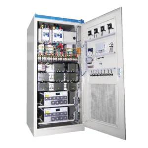
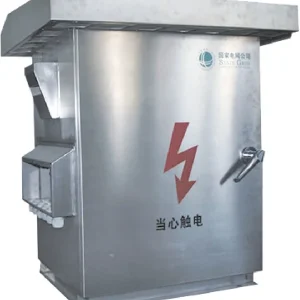
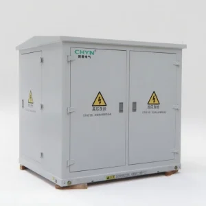
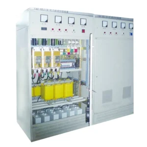
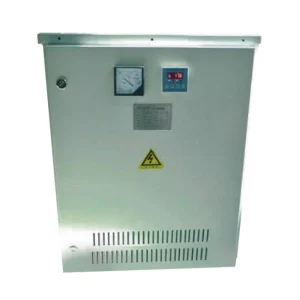
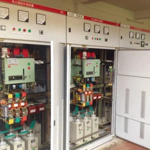
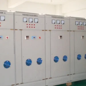
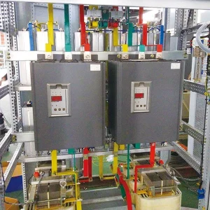
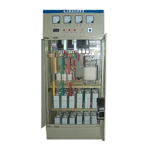
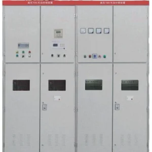
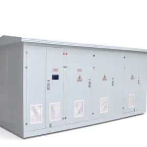
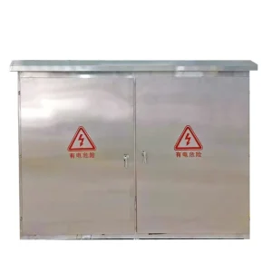
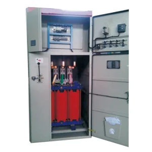
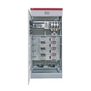
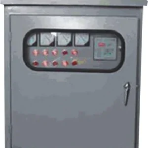
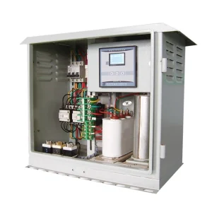
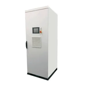
The CHYN outdoor low-voltage compensation cabinet is one relevant assembly family for outdoor distribution projects. Its exterior photograph does not reveal the capacitor frequency rating or internal branch design. Request the offered assembly's component schedule and approval for the destination supply. Do not infer 50/60 Hz interchangeability from the cabinet shape or family name.
Calculate the frequency effect with clear assumptions
For an ideal capacitor supplied by a sinusoidal RMS voltage, capacitive reactance is XC = 1/(2πfC). Current magnitude is I = V/XC = 2πfCV. The reactive-power magnitude of that element is consequently Q = 2πfCV². Use hertz for f, farads for C, volts RMS for V and var for Q. The reactance relationship is explained in OpenStax's treatment of capacitive and inductive reactance.
For the same capacitance and unchanged connection, the ratio is Q₂/Q₁ = (f₂/f₁)(V₂/V₁)². Here both voltages must describe the same electrical quantity, such as the voltage across the same capacitor element. This prevents a common error in which one side uses line voltage and the other uses phase voltage. Convert units consistently before performing the calculation.
At the same voltage, 60/50 = 1.20. A hypothetical plain bank producing 100 kvar at 50 Hz would therefore produce approximately 120 kvar at 60 Hz under the ideal assumptions. At the same voltage and 50 Hz instead of 60 Hz, a hypothetical 100 kvar bank would produce about 83.3 kvar. These are calculated examples, not CHYN product ratings, test results or permission to change the supply.
Voltage changes can outweigh the frequency change. For a hypothetical 100 kvar, 400 V, 50 Hz plain bank, use at 480 V and 60 Hz would calculate as 100 × (60/50) × (480/400)² = 172.8 kvar. That large calculated increase is a reason to stop and request a rating review. It does not establish that the capacitor can withstand the higher voltage or that the complete assembly can carry the resulting current.
Use a comparison table without turning it into an approval
| Illustrative change | Calculated Q₂/Q₁ | What still needs approval |
|---|---|---|
| 50 to 60 Hz; same voltage | 1.200 | Capacitor frequency duty and complete branch current rating |
| 60 to 50 Hz; same voltage | 0.833 | Delivered compensation and all frequency-sensitive components |
| 400 to 480 V; same frequency | 1.440 | Rated voltage, insulation and resulting current |
| 400 V/50 Hz to 480 V/60 Hz | 1.728 | Entire assembly selection for the destination supply |
| Any change to a reactor-capacitor branch | Simple scaling not sufficient | Combined impedance, capacitor voltage and harmonic assessment |
Every numerical row assumes fixed capacitance, the same connection and an ideal unreactored branch. The values are derived from the preceding equation. They are not manufacturer derating factors or recommended operating limits. The purpose is to expose the questions an application review must answer before someone reuses existing equipment.
For broader capacity planning, see how to size a capacitor bank. That sizing decision must use the required compensation at the actual operating conditions. A nominal kvar figure from a different frequency or voltage basis is not the delivered compensation at the new site.
Why a detuned branch needs a separate assessment
An inductor's reactance rises with frequency while a capacitor's reactance falls. Their combined behavior therefore changes when the fundamental supply frequency changes. The physical resonance frequency of a fixed ideal L-C combination is fr = 1/(2π√LC). It stays tied to the component values, while its harmonic order relative to the supply changes with the fundamental frequency. The resonance relationship is listed in the OpenStax AC circuit equations.
The Duke University explanation of frequency and capacitor impedance provides the physical background for the capacitor part of this behavior. In an actual detuned assembly, ask the designer to assess the full branch using the real inductance, capacitance, tolerances, losses and supply spectrum. Do not transfer a percentage-reactance label between projects without checking its frequency basis.
This article does not select a reactor percentage or claim that one tuning choice suits every destination. The related detuned reactor guide explains why that percentage needs an application context. Review the capacitor terminal voltage, expected harmonic currents and protective arrangement together. Keeping the same capacitor kvar while changing only a reactor can invalidate the original coordination.
Review the devices surrounding the capacitors
A frequency label on a capacitor is only part of the equipment record. Check the declared duty of the switching devices and the control supply, including any frequency-sensitive coils or transformers. Review conductors, branch protection and enclosure thermal duty against the revised current. A correctly calculated kvar output does not prove that those components remain within their ratings.
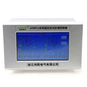
Ask how the controller measures frequency and reactive power and whether its configuration matches the proposed supply. The required stage sizes also deserve a fresh review: increased output can make the smallest step too large for a lightly loaded transformer. Avoid copying the previous site's switching thresholds without comparing the new demand profile and control objective.
The capacitor-bank contactor selection guide covers a complementary issue: declaring switching duty rather than relying on a motor-current label. For a frequency conversion, retain that discipline. Obtain an approved component schedule instead of assuming that a larger current marking resolves all capacitor-switching conditions.
Verify the destination supply and document the decision
For an export order, identify the actual installation supply instead of assuming it from the destination country. Industrial plants can have special networks, generators and multiple voltage levels. Send the nominal frequency, expected operating range, nominal voltage, connection, available fault level and harmonic measurements where available. Identify transformer or generator operation separately if those modes change the application.
For an existing bank, retain the original drawings and photograph each relevant nameplate during an approved inspection. Record the exact replacement proposal and why the change is needed. Missing component information is a request for further investigation, not evidence that the component is universally compatible. Electrical inspection and stored-energy procedures must be performed by qualified personnel following the applicable equipment instructions.
Ask the supplier to return a written selection showing delivered stage kvar at the destination voltage and frequency, capacitor element ratings, reactor selection where applicable, switching and protection coordination, and the acceptance test. Keep the calculation sheet with that response. It should be possible for a later maintenance team to distinguish the calculation assumptions from the approved operating conditions.
Further learning: reactive power in AC circuits
The following NPTEL lecture explains active and reactive power in AC circuits. It helps interpret the quantities used in this article. Its educational examples do not replace the manufacturer's assessment of a capacitor bank at a different supply frequency.

Watch Lecture 30: Concept of Active and Reactive Power in A.C Circuit - II on YouTube.
Frequently asked questions
Does a 50 Hz capacitor bank deliver the same kvar at 60 Hz?
Not for unchanged ideal capacitance and voltage. The simple unreactored calculation gives 1.20 times the reactive power at 60 Hz. That result predicts demand only; it does not prove that the capacitor, switching devices, protection or complete assembly is approved for the changed frequency.
Can I convert kvar using frequency alone?
Only when the comparison keeps capacitance, connection and voltage unchanged under the ideal unreactored assumptions. If voltage changes, include its squared ratio. If the branch includes a series reactor, request a combined branch assessment instead of treating the plain-capacitor ratio as the complete design calculation.
Does a 50/60 Hz label approve the entire cabinet?
A label applies to the equipment identified by its documentation. A dual-frequency capacitor does not automatically establish the suitability of every coil, transformer, controller or reactor in the cabinet. Obtain the complete assembly’s declared operating conditions and coordinated component schedule for the destination installation.
What information should an export quotation include?
Provide the actual site voltage and frequency, wiring arrangement, compensation demand, source information and harmonic conditions. Identify any generator operating mode. Ask for delivered stage kvar at the destination conditions and written component coordination rather than comparing suppliers only by a nominal total kvar figure.