
 Zhejiang Hongyan Electric Co., Ltd.
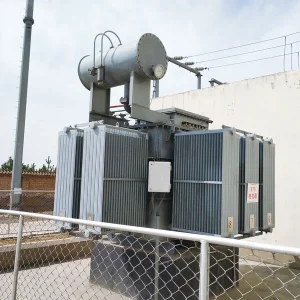
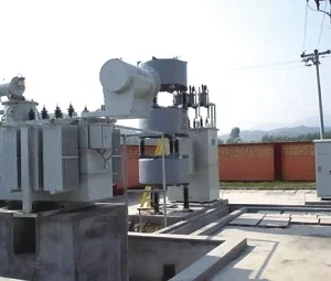
Dynamic voltage restorer transformer inrush should be investigated by identifying which transformer is involved and when its current rises relative to voltage injection. In a transformer-coupled DVR, the injection transformer can experience a transient flux offset when compensation starts. A downstream load transformer can also draw magnetizing current during energization or voltage recovery. These events need different evidence and remedies. A large current trace alone does not prove that the DVR is undersized, and increasing an overcurrent setting is not a substitute for determining the cause.
This article focuses on the magnetic transient and its commissioning evidence. For the broader disturbance requirements, begin with a voltage-sag ride-through specification. Define the topology and operating sequence before comparing a proposal with a current waveform.
Identify the injection transformer and the load transformer
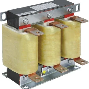
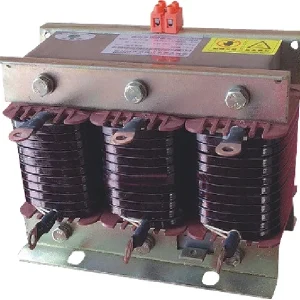
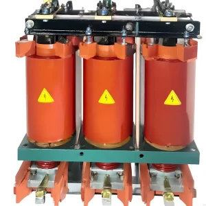
A series injection transformer transfers the converter's compensating voltage into the protected circuit in a transformer-coupled arrangement. A downstream power transformer serves the load. They occupy different positions and need separate identifiers on the single-line diagram. A report referring only to “transformer inrush” leaves the location of the suspected event unresolved.
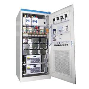
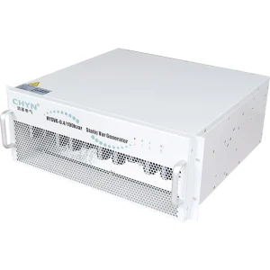
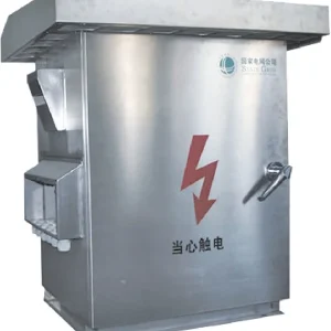
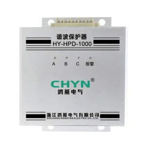
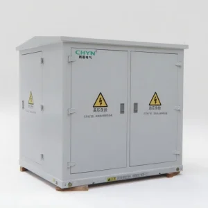
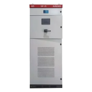
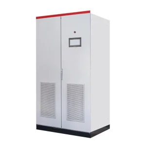
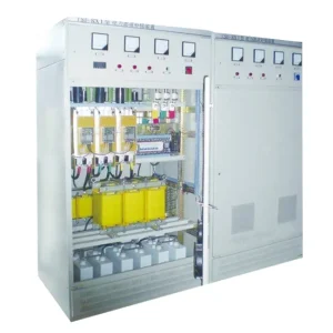
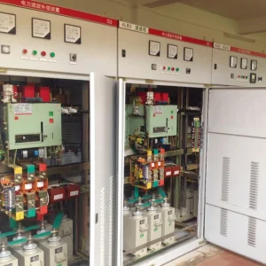
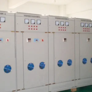
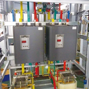
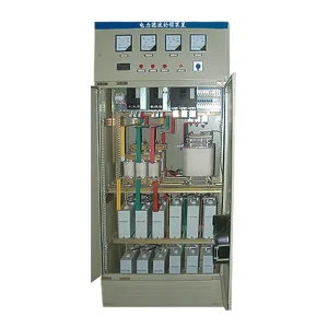
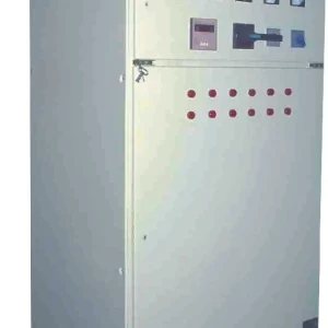
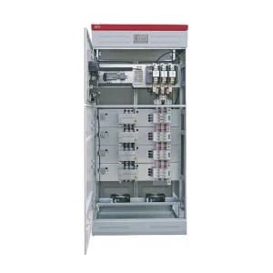
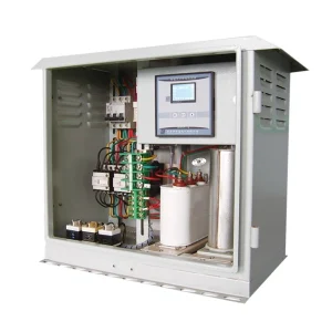
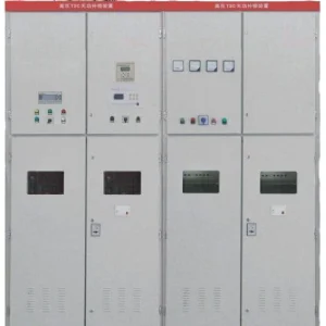
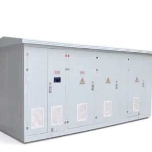
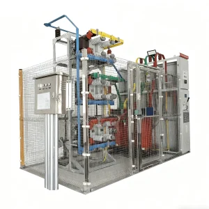
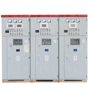
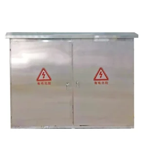
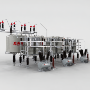
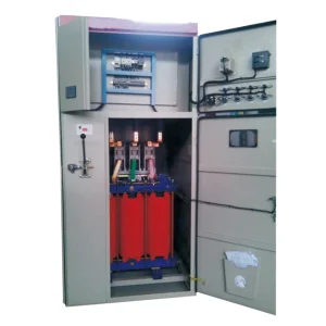
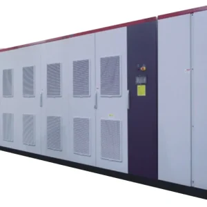
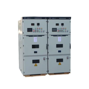
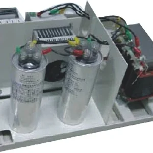
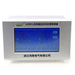
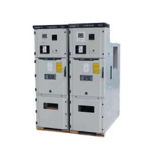
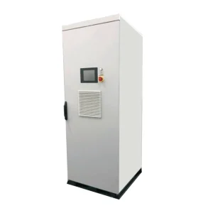
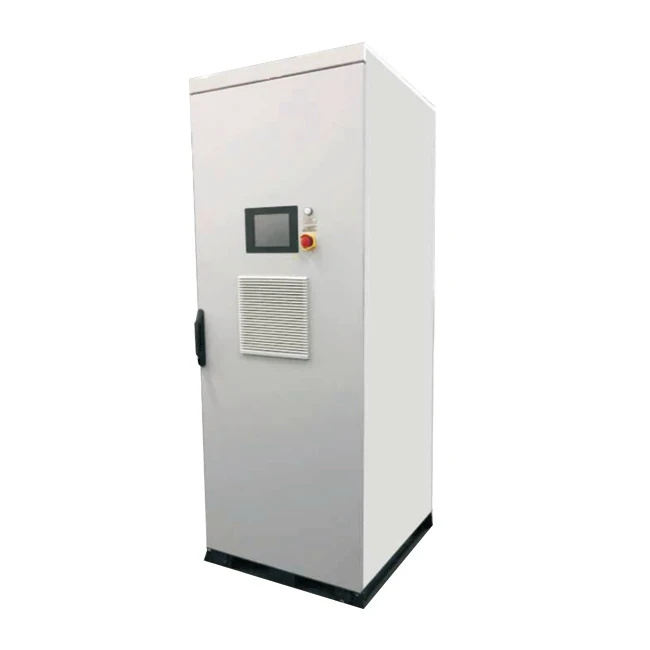
The CHYN HYDVR voltage-sag mitigation family is relevant to this application. Request the actual offered topology, injection connection and protection arrangement. A cabinet photograph or a product-family capacity table does not demonstrate a specific transformer design or an implemented flux-control method.
Mark where each current was measured: converter output, injection winding, protected feeder or downstream transformer primary. Include current direction and the sensor ratio. The currents cannot simply be compared as if every trace represents the same winding. When measurements come from separate instruments, reconcile their clocks before interpreting the sequence.
Understand why voltage injection can create a flux offset
For a simplified winding model neglecting winding resistance and leakage effects, the change in flux linkage is Δλ = ∫v(t)dt. Flux linkage λ is measured in volt-seconds, equivalently weber-turns; v is winding voltage in volts and time is in seconds. Magnetic flux is λ divided by the number of turns. The integral and the initial magnetic state matter, not only the RMS voltage.
A research record from the University of Manchester on DVR transformer saturation identifies elevated transient flux linkage when sag compensation begins and describes a method to limit it. This supports reviewing the starting transient. It does not establish that the same research method is fitted to a CHYN product.
As a deliberately simplified calculation, a net voltage integral of 0.020 volt-seconds changes flux linkage by 0.020 weber-turns. If the hypothetical winding had 100 turns, the corresponding flux change would be 0.00020 webers. These numbers illustrate units only. They cannot predict saturation without the actual turns, core area, initial flux, winding losses and magnetic characteristic.
Distinguish three event sequences
First, a current rise at the instant of injection may point toward the injection transformer or the converter's transition into compensation. Second, a rise associated with closing a downstream transformer may be a load-energization event. Third, a rise after the upstream supply recovers may involve voltage recovery, controller transition or the downstream magnetic state. Treat these as investigation paths rather than diagnoses.
The Aalborg University thesis Design and Control of a Dynamic Voltage Restorer discusses transformer-connected DVR design and the influence of voltage application, initial flux and magnetic characteristics. Its modeled and experimental arrangements provide technical background; their ratings and results are not acceptance values for another installation.
Ask whether the plant remained connected throughout the sag or whether contactors opened and subsequently reclosed. A downstream reconnection changes the event being studied. Production control logs can therefore be as important as the DVR alarm list when a current transient appears near the end of a disturbance.
Build a synchronized event record
| Signal or record | What it helps separate | Detail to preserve |
|---|---|---|
| Supply and load voltage waveforms | Incoming sag, injected correction and recovery | Phase labels, timestamps and sensor location |
| Commanded and measured injection voltage | Controller request from actual response | Winding reference and the transition interval |
| Injection-transformer current | Local magnetic transient from downstream current alone | Sensor ratio, measurement bandwidth and scaling |
| Downstream transformer breaker or contactor state | Continuous connection from fresh energization | Actual contact indication and event ordering |
| Converter and bypass states | Compensation from limiting, blocking or transfer | First initiating event and subsequent state changes |
| Protection records | Measured stress from a later protective consequence | Pickup, operation, configured logic and approved settings |
This table proposes evidence to collect, without prescribing universal current or timing limits. The magnetic relationships above motivate the waveform review; the supplied equipment capability and project protection study determine acceptable behavior.
Verify the measurement before interpreting a current peak
Obtain the original waveform file where possible, rather than relying on a photograph of a peak-hold display. Record the sampling method and whether the current value is instantaneous, cycle RMS or another processed quantity. A narrow transient and a sustained overload can produce very different equipment duties despite a similar displayed maximum.
Check for clipped traces and sensor limitations. An apparent flat-topped waveform may reflect measurement range rather than the equipment current itself. Confirm polarity, ratio and phase labels using the approved test procedure. Do not infer magnetic saturation from waveform appearance alone when the measurement chain has not been assessed.
Retain pre-event data as well as the compensation interval. The starting operating condition and previous switching sequence may matter to the interpretation. If the recorder began after the trip, state that the initiating event was not captured. A missing onset should remain an evidence limitation, not become a confident diagnosis.
Review the design response with the supplier
Ask how the supplied design manages injection-transformer magnetic transients across the specified sag depth, onset conditions and recovery sequence. Request the applicable design explanation and test evidence. The answer may depend on transformer design and control behavior; a generic statement of fast response does not resolve the flux question.
If a controlled voltage transition is proposed, review its effect on the protected load voltage as well as the current. A change that reduces one transient may alter the restoration waveform seen by a sensitive process. Acceptance needs both the equipment operating within its permitted envelope and the load receiving the agreed voltage performance.
Do not assume that a software feature can be added safely to existing hardware. Record the installed firmware, approved settings and supported options. Any proposed change should include supplier authorization, the relevant protection review and a retest plan. A research control strategy is a starting point for questions, not a field modification instruction.
Keep bypass coordination and current capability in the review
Trace the actual protection sequence to determine whether the first event was a current limit, converter block, bypass action or upstream trip. Review the relationship between these events using DVR bypass protection. A bypass transition can explain a later voltage change without explaining the original current rise.
Separate peak current, duration and repetition when discussing capability. A load's normal kVA does not describe every short-duration duty. Provide the supplier with the downstream transformer details and permitted switching modes, and request confirmation for the defined operating scenarios. Avoid extrapolating a continuous-current rating into an unlimited transient allowance.
If the existing arrangement cannot support a required sequence, document the restriction while the engineering review proceeds. Changes might involve an approved operating sequence or equipment design, but the choice requires project evidence. Raising a protective limit merely to avoid an alarm can leave the original stress unaddressed.
Define a witnessed test that answers the disputed question
Use a supplier-approved test plan that specifies the disturbance, initial operating state, measured channels and stopping conditions. Where actual transformers or sensitive production loads are involved, the responsible parties must agree the test method and exposure. Do not create uncontrolled sags or switching events on a live production network to obtain an illustrative waveform.
The plan should cover the operating cases within the contracted scope and identify exclusions. Record which initial states, sag profiles and recovery sequences were actually exercised. One successful event at one operating point cannot validate every possible sag or switching condition. Keep modeled predictions separate from witnessed observations.
Close out through the DVR acceptance-test record, with synchronized waveforms, configuration identity, protection outcomes and load behavior. If the cause remains uncertain, list the missing measurement explicitly. A useful report narrows the next investigation instead of declaring that every unexplained peak is ordinary inrush.
Further learning: voltage-sag mitigation
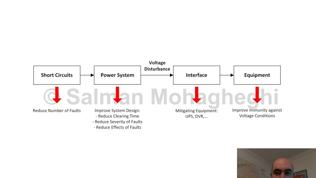
The lecture below by Salman Mohagheghi explains mitigation of voltage sags and interruptions. It gives context for the DVR's series compensation task. It does not demonstrate a CHYN transformer saturation test or establish a product-specific transient-current limit.
Watch the educational lecture on YouTube.
Frequently asked questions
Is every DVR current peak injection-transformer inrush?
No. Identify the measurement location and event timing. Downstream energization, overloads, faults, control transitions and measurement limitations may require separate investigation.
Can RMS voltage alone predict magnetic saturation?
No. The voltage waveform integral and initial magnetic state matter, along with the actual transformer design. RMS voltage alone does not capture the complete transient.
Should overcurrent protection be increased to stop trips?
Only an authorized engineering review can approve a change. First identify the initiating event and verify equipment capability, protection coordination and the required retest.
What evidence should an acceptance report include?
Include topology, configuration, synchronized voltage and current waveforms, switching states, protection records, tested conditions and any limitations or untested operating cases.