
 Zhejiang Hongyan Electric Co., Ltd.





































An active harmonic filter diagram shows a cabinet in parallel with a distorted load, measuring that current and injecting an opposing current so the supply current is what remains. The useful drawing names the nonlinear load, the current transformer, the controller, the PWM inverter, the DC bus, the coupling reactor, and the injection point. The walk below follows that order, then shows how current-transformer placement changes the measurement and when the matching product page is the next sheet to open.

What the drawing is actually showing
The usual low-voltage drawing is a shunt active power filter sitting beside the load, not a series box dropped into the feeder. Current leaves the supply, splits toward the load and toward the filter, and the filter pushes a canceling current back at the same node. Read it as a signal path first and as a cabinet outline second.
Four arrangements show up in technical notes, and they change what the page is solving. A shunt drawing targets current. A series drawing puts a transformer in the line and targets voltage.
A hybrid drawing keeps a tuned passive branch for the heavy orders and an active stage for the rest. A unified conditioner draws both a series path and a shunt path on one DC circuit.
Most plant one-lines you will actually hold are the first kind. If the filter symbol has no series transformer and the cable returns to the same bus as the load, you are looking at a shunt path. The rest of this page walks that path.
| Block on the drawing | What it is doing | What a missing label leaves unanswered |
|---|---|---|
| Nonlinear load | Draws the distorted current | Which machines the sensor is supposed to see |
| Current transformer | Copies that current for the controller | Which cable the sensor is clipped on |
| Controller | Builds the compensating reference | Whether it is watching load current or supply current |
| PWM inverter | Switches the DC bus into the requested current | Which bridge is in the cabinet |
| DC bus | Holds the energy the inverter switches | That the capacitor is the buffer, not a battery sketch |
| Coupling reactor | Shapes the current between inverter and bus | Why the output is not a bare copper link |
| Injection point | The node where the canceling current enters | Which bus the cable actually lands on |
Where the nonlinear load sits on the page
The distorted current starts at the load. Drives, rectifiers, UPS inputs, and similar equipment pull current in pulses even when the voltage still looks smooth. The cabinet is drawn in parallel so it can supply those pulses instead of leaving them for the upstream transformer.
Three currents matter, and good drawings keep them separate. Load current is what the machines take. Injected current is what the filter adds.
Source current is what the supply still has to provide after those two meet. If the cartoon only shows one arrow into the cabinet, ask which of the three it is.
A plant example makes the split obvious. A motor-control lineup of variable-speed drives sits on one feeder. The filter cabinet is paralleled at that bus, not inserted in series with every drive.
The drives remain the harmonic source. The cabinet is the opposing source.
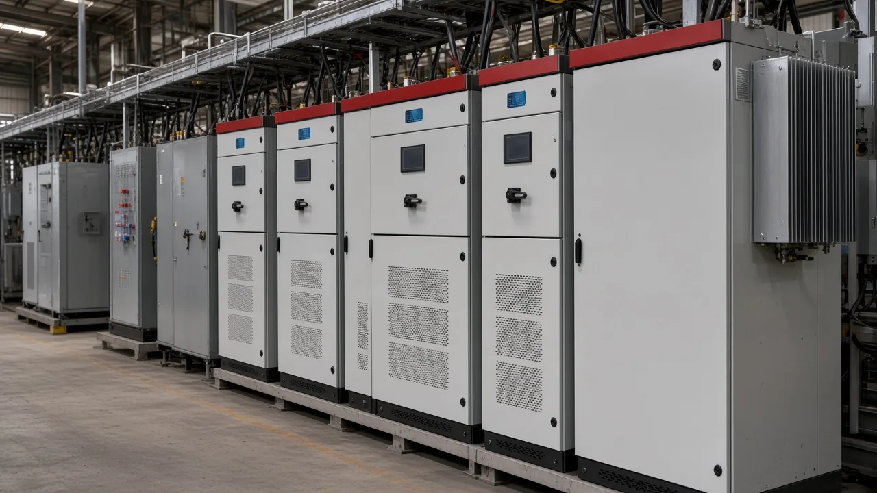
Passive branches work differently, and that contrast is short on purpose. A tuned passive circuit is a reactor and capacitor aimed at one harmonic order, so a fifth-harmonic branch does not automatically clean a seventh.
The active drawing is a converter that rebuilds a spectrum. Choosing between them is a different job from reading the blocks.
How the current transformer talks to the controller
The current transformer copies load current into the controller. On a published shunt description the sensor sits on the load current, a processor picks out the harmonic part, and that result becomes the reference the inverter must follow. Without that copy, the power stage has nothing to oppose.
The controller is the calculation block, not the handle on the door. Frequency-domain methods such as a Fourier split, and time-domain methods that peel the oscillating power off the fundamental, both end at the same practical output: a current reference that is the unwanted part of the load current, reversed.
The drawing does not have to name the algorithm. It does have to show a measurement entering a controller and a reference leaving toward the switches.
Direction and phase matter as much as the clip-on location. If the sensor is reversed, the cabinet injects with the distortion instead of against it. A small polarity mark on the one-line is more useful than a second paragraph of product adjectives.
How active harmonic filter works is the same loop written in words: measure the distorted current, compute the unwanted part, switch a canceling current, and check the result. The diagram is that sentence drawn as boxes.
A forum reply notes that a DSP is often already there to manage PWM, so the usual controller digitizes and analyzes the current waveform.
From the field: An engineer looking for an active power filter circuit diagram was told the hard part is controls that work reliably, rather than the power electronics circuit (circuit diagram of an active power filter).
What the PWM inverter and DC bus are doing
The PWM inverter builds the canceling current by switching the DC bus. Pulse-width modulation turns the controller reference into gate signals for the IGBT bridge.
The bridge does not store the harmonic energy by itself. It steers voltage so current moves through the output inductors in the shape the reference asked for.
The DC bus on a voltage-source inverter is a capacitor. A current-source inverter uses an inductor in that same DC circuit instead, which is a different cartoon.
Unstable DC-link voltage degrades the filter, so the controller is expected to regulate that voltage. A correct diagram shows a voltage loop into the current reference.
A three-level bridge, when the product page says the cabinet uses one, is still this same block. It changes how the switches are stacked and how much ripple the reactor has to clean. It does not add a second injection point.
How the coupling reactor meets the injection point
A coupling reactor sits between the inverter terminals and the bus. A university paper notes that a typical drawing uses series inductors, and that an LCL ripple filter adds a capacitor shunt branch when the designer is cleaning switching ripple. That inductor is the output reactor, filter inductor, or coupling reactor on the bill of material.
The name changes. The job does not.
The injection point is the node where that current enters the system, often the same bus the load uses. If the cable lands upstream of the sensor, or on a different feeder, the controller and the bus are no longer looking at the same current. The one-line has to show the landing, not only the cabinet rectangle.
LCL design has to watch current ripple, resonance, and the reactive power the capacitors absorb. The interface on a shunt drawing is that reactor path. A bare lug from the IGBT terminals to the bus skips the interface the paper describes.
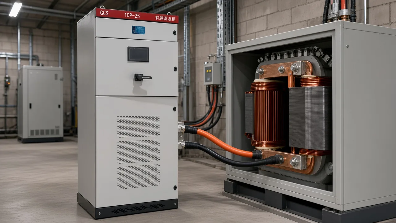
Read the landing against the job, not against a stock cartoon. A bus-applied cabinet is meant to sit in parallel with several loads on one bus. A unit drawn only across one drive feeder is a different injection point, even if the internal blocks look identical.
How CT placement changes the measurement
A load-side current transformer sees the distorted current before the injection mixes in. The controller then builds an opposing current from that copy. A supply-side sensor sees the current that remains after injection, which is a different measurement.
Some drawings show both, and the labels are the whole point.
| Sensor place | What the controller sees | How to read the arrow |
|---|---|---|
| Load side, between the split and the machines | The distorted load current | Open measurement of the problem current |
| Supply side, upstream of the split | Source current after injection | Closed check of what the bus still carries |
| Two sets, load and filter output | Load current inferred by subtraction | Used when several modules share one bus sensor |
| Unlabeled clip on the cable | Unknown | Stop and mark the cable before anyone wires it |
The filter current itself has a ceiling. A published review lists limitations of maximum currents and voltages among the disadvantages of these units.
A block diagram that omits amperes cannot promise a clean wave. The rating lives on the schedule, not in the rectangle.
Two sets of sensors are not a drawing error by themselves. They become an error when nobody writes which set is the reference and which set is the check.
Parallel modules often share one load-side set so they do not fight each other. That sharing still has to be on the page.
When the HYAPF product page is the drawing to open next
Open the HYAPF Series Active Power Filter when the one-line is a low-voltage shunt cabinet that measures load current and injects an equal, opposite harmonic current beside nonlinear industrial or commercial loads. The series page also states support for reactive-power or load-imbalance compensation. That is the same job the blocks describe, written as a product record.
On the live HYAPF Series page the published rows are rated voltage 400 V / 690 V optional, harmonic compensation from the 2nd through the 51st order, response time under 10 ms, control accuracy THD under 5%, and switching frequency up to 20-30 kHz.
| Published row | What the page states |
|---|---|
| Topology | Modular three-level design |
| Rated voltage | 400 V / 690 V (optional) |
| Harmonic compensation range | 2nd–51st order |
| Response time | under 10 ms |
| Control accuracy | THD under 5% |
| Switching frequency | Up to 20-30 kHz |
Those rows do not replace the injection point, the sensor cable, or the reactor on your one-line. They tell you the electrical window the series page actually publishes. A drawing of a series transformer, a passive tuned branch, or a high-voltage static-var job points elsewhere on the Active Power Filter Series hub, which also lists static var generators and hybrid devices for fast harmonic, reactive-current, and imbalance work.
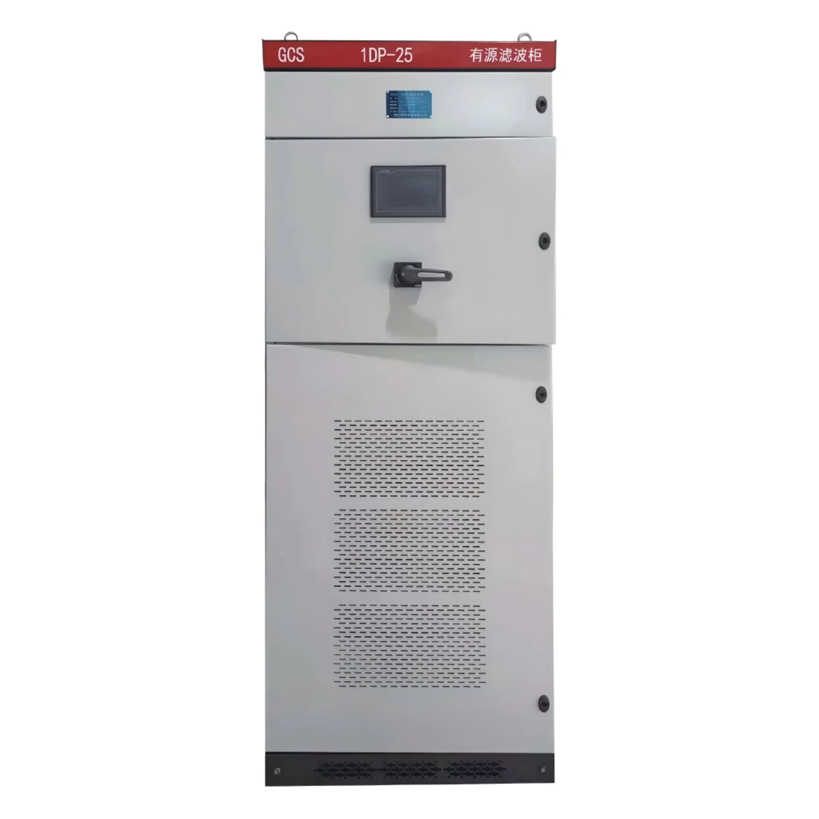
A manufacturing plant with several drive lineups is the usual place this reading pays off. The solution note for manufacturing plant power quality is the application context. The diagram still has to be the job one-line, with the sensor and the landing marked, before anyone treats the catalog cabinet as the installed layout.
FAQ
Why is the current transformer drawn outside the cabinet?
The sensor has to sit on the current the controller is supposed to read, and that current is on the bus or feeder, not inside the power stage. An external current transformer is how the drawing shows that copy. If the clip is drawn on the cabinet door instead of on a cable, the page has not finished the measurement.
Does the inverter block need a separate DC power source?
Usually no. The DC bus on a voltage-source inverter is a capacitor, and the controller is expected to regulate that voltage.
A drawing that shows neither a capacitor nor a voltage loop has not finished the block.
What is the coupling reactor doing that a plain cable would not?
It sits between the switched inverter voltage and the bus so the current can be shaped. A plain cable would tie the bridge terminals hard to the bus. The reactor is the interface people are looking for when they ask how the compensating current is allowed to enter.
Why do some drawings show two sets of current transformers?
One set often copies load current for the reference. The other copies supply current or filter output as a check, or so several modules can share a bus sensor and subtract. Two sets are readable only when each set is labeled with the cable it sits on.
Is a three-wire drawing the same as a four-wire drawing?
No. A three-wire drawing has no neutral conductor in the filter connection. A four-wire drawing includes the neutral, which is where third-order and unbalance current can return.
Match the drawing to the system the cabinet will land on, and keep the extra wire only when the system has a neutral.
Can a block diagram tell me the filter ampere rating?
No. The blocks show the path. Amperes, order-by-order headroom, and how many modules share a sensor live on the schedule and the product rows.
A rectangle with no current rating is silent on whether the cabinet can carry the harmonic current you measured.
What should I ask before treating a stock diagram as the job drawing?
Ask which cable the current transformer is on, which bus the reactor lands on, whether the system is three-wire or four-wire, and what compensating current the schedule expects. A stock cartoon that omits those four marks is a teaching sketch, not the installation sheet.
References
- San Diego State University paper on the series-inductor and LCL interface of a shunt active power filter
- Energies review of shunt active power filter diagrams, functions, and current limits
- Physics Forums thread on an active power filter circuit diagram
- Physics Forums thread on extracting the cancellation waveform in the controller