
 Zhejiang Hongyan Electric Co., Ltd.
A capacitor bank blown fuse is a reason to investigate the protected circuit before restoring service. It may indicate a failed capacitor unit, another circuit fault or an operating condition that needs review; the open fuse alone does not establish the cause. Preserve the event records, identify the bank configuration and follow the approved isolation and stored-energy procedure. Qualified personnel should then inspect the affected equipment and compare findings with the protection and replacement documentation. Do not fit a larger fuse, bypass it or repeatedly re-energize the bank to find out what happens.
Identify what the fuse actually protects
Start with the approved single-line diagram and physical equipment identification. Determine whether the indication concerns a feeder fuse, a step fuse, an external capacitor-unit fuse or an auxiliary control fuse. These locations have different implications. A control-circuit fuse may stop automatic operation without proving a capacitor failure, while a capacitor-unit fuse belongs to a different protection boundary. Avoid ordering parts from an alarm description without first confirming the device and circuit.
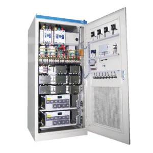
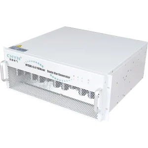
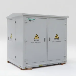
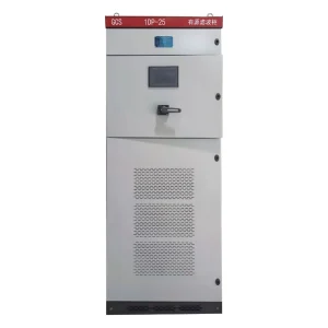
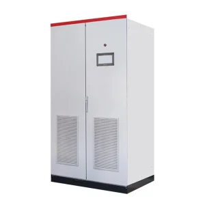
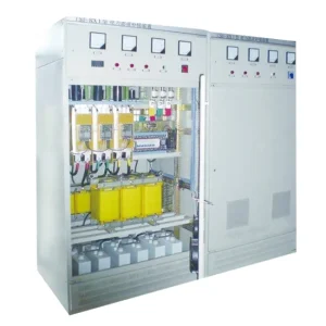
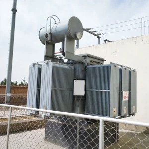
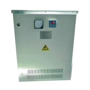
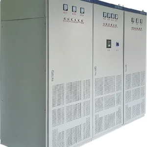
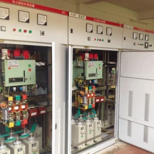
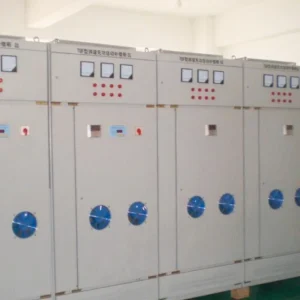
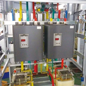
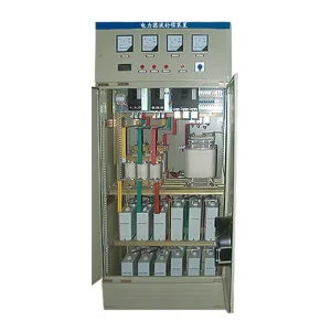
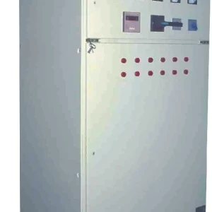
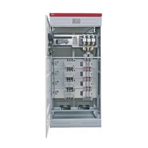
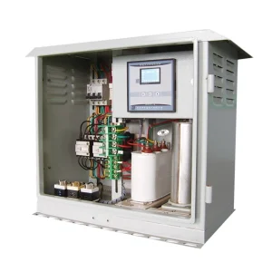
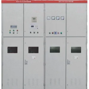
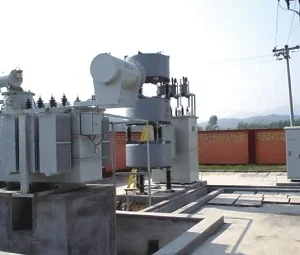
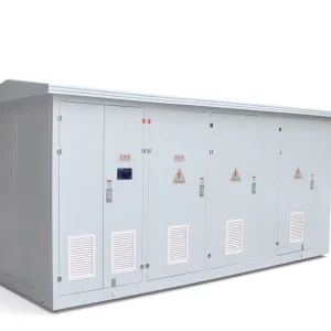
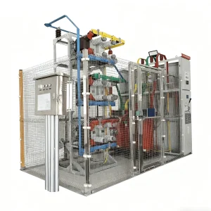
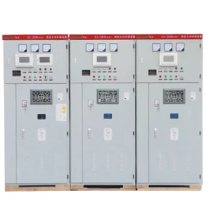
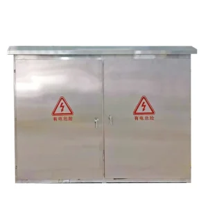
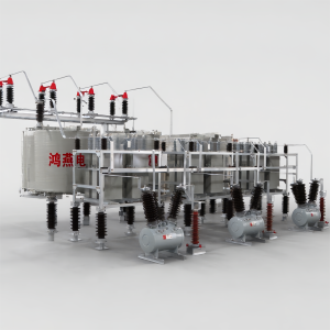
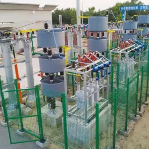
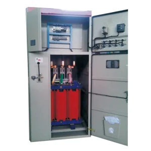
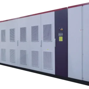
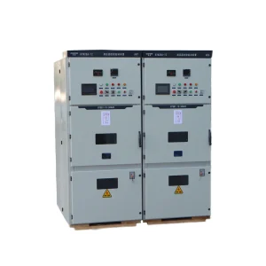
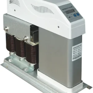
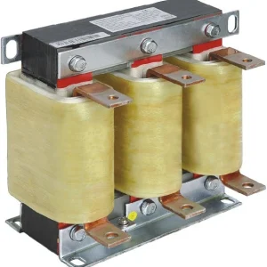
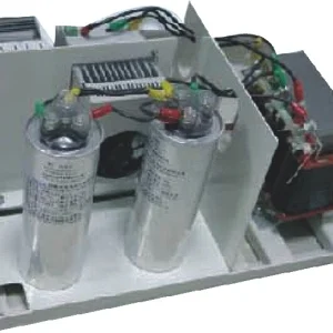
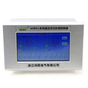
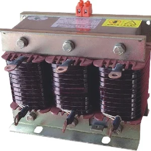
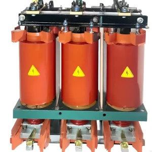
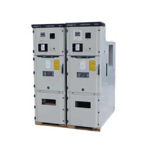
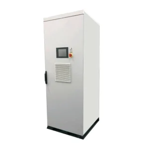
Record the bank voltage, connection, unit arrangement, grounding method and whether capacitors are externally fused, internally fused or fuseless. The CHYN HYTBB medium- and high-voltage compensation equipment is a relevant product reference for an enquiry. Its photograph does not reveal every internal connection or establish the fuse requirements of a delivered bank. Use the actual drawings and serial-number documentation.
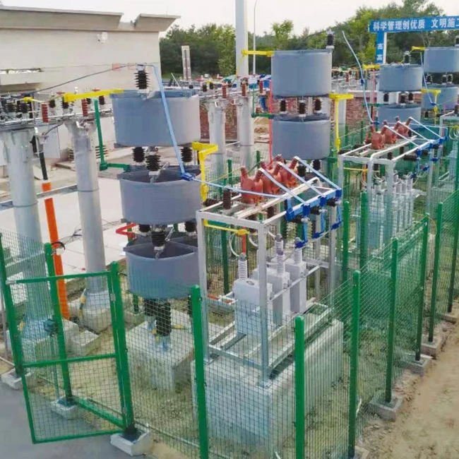
For background on one arrangement, see externally fused capacitor banks. Distinguishing the arrangement is the first diagnostic step, because a replacement decision that makes sense for one topology may not apply to another. An inaccessible internal element fuse is not an external service part that maintenance personnel can simply replace.
Preserve the evidence before resetting alarms
Save the event time, switching commands, relay targets, recorded currents and voltages, and relevant controller alarms. Identify which other capacitor steps were energized and whether a nearby feeder or transformer also changed state. Ask operators whether this was the first occurrence or a repeat after previous repairs. Preserve previous fuse part numbers and any setting changes so the investigation can distinguish the original design from later substitutions.
Event timing helps organize questions without proving an answer. An operation immediately after switching calls for a different review from one after a long operating period. A disturbance following maintenance also warrants checking the recorded work and approved restoration steps. Keep these as hypotheses until supported by inspection, measurements and the applicable equipment data. Do not describe an event as nuisance operation merely because the capacitor case looks normal.
Compare the event with the bank’s commissioned baseline. Identify measurement locations and ratios, not just displayed amperes. A feeder measurement can combine several branches and may not identify the affected unit. If the available records are insufficient, document that gap and define the next safe investigation rather than filling it with assumptions.
Respect stored energy even when the fuse is open
The U.S. Department of Energy’s Electrical Safety Handbook, section 13.5.1, discusses capacitor hazards, fusing and discharge arrangements in its R&D-equipment context. It specifically highlights the significance of fuses in discharge paths. An open circuit must not be treated as proof that every capacitor has discharged. The handbook is background guidance; the site’s applicable rules and approved equipment-specific work procedure govern the task.
Only qualified personnel should establish isolation, verify the absence of hazardous voltage and apply the required discharge and grounding provisions. This article does not prescribe a universal waiting time, grounding sequence or test voltage. A timer expiring, an extinguished indicator or a controller showing “off” is not independent proof of a safe work condition. Include auxiliary and possible backfeed sources in the work plan.
If a unit is damaged or its condition is uncertain, refer handling and removal to the responsible specialists. Keep the equipment identification attached to the investigation record. Do not open sealed capacitor units or attempt improvised internal repairs. Transport and storage decisions also require the approved procedure, particularly where internal damage or residual charge is a concern.
Use a diagnosis table without turning clues into conclusions
The following table is an investigation organizer. None of these observations alone authorizes re-energization. The next action should be chosen by the responsible engineer using the bank drawings, event evidence and manufacturer’s requirements.
| Observation | Question to investigate | Useful evidence | Decision boundary |
|---|---|---|---|
| Fuse operated near switching | What switching sequence and circuit conditions existed? | Time-aligned commands, waveforms and energized-step status | Do not assume transient operation without reviewing the protected equipment |
| Repeated operation in one position | Is the affected unit, connection or protection selection unresolved? | Position history, isolated inspection and approved part records | Do not increase the fuse rating to suppress recurrence |
| Unbalance alarm with an open fuse | How does this bank topology translate the missing circuit into the measured signal? | Connection drawing, relay quantities and baseline readings | Do not copy another bank’s alarm or trip setting |
| No visible case damage | What approved checks establish unit condition? | Manufacturer-directed measurements and comparison records | Appearance alone does not establish serviceability |
Interpret unbalance through the actual bank topology
The technical paper Capacitor Bank Protection for Simple and Complex Configurations, published by SEL’s authors for a protection-engineering conference, explains how protection methods depend on connection and instrument-transformer placement. It also distinguishes element and unit failures. This is a technical reference rather than an endorsement of a relay product or a source of universal settings.
Use that distinction when interpreting the site record. Ask the protection engineer which failure the measured quantity can detect and whether natural unbalance or the operating state affects its interpretation. Record the relevant baseline and the current configuration. A successful relay test at commissioning does not establish that today’s physical bank still matches the approved connection and compensation assumptions.
For a broader discussion of setting relationships, refer to capacitor-bank protection coordination. Keep this investigation focused on the operated fuse and the cause of the event. Do not alter relay thresholds merely to clear an alarm created by a missing or damaged circuit.
Inspect and test against approved criteria
Once the safe work condition is established, document the affected fuse position and the associated components before changing anything. Follow the approved inspection scope for connections, holders, insulators, conductors, capacitor units and other equipment within the protected boundary. Record damage, contamination or unusual indications with their exact locations. Photographs are useful evidence, but they should accompany component identifiers and findings rather than replace them.
Use manufacturer-directed tests and acceptance criteria appropriate to the unit construction. Preserve the instrument identification, configuration, measurement conditions and comparison basis. A disconnected unit measurement and a bank-terminal measurement are not automatically comparable. If a result falls outside the accepted range or cannot be interpreted reliably, keep that item open for engineering review.
Distinguish the failed part from the reason it failed. Replacing a damaged holder may be necessary, but the investigation should still address why that position was affected. Similarly, a capacitor found outside its accepted criteria does not eliminate the need to review the event and remaining equipment. Avoid closing the record with “fuse replaced” when the initiating cause remains unknown.
Match the replacement to the approved protection design
A replacement request should include the original manufacturer and part designation, voltage and current ratings, interrupting capability, time-current characteristic and physical arrangement. Supply the bank and capacitor-unit data, drawings and relevant fault-level information. The responsible engineer should confirm compatibility with the protected equipment and upstream protection. Matching only the ampere marking is not a complete substitution review.
If the original part is unavailable, obtain written approval for the proposed alternative and preserve the comparison. Do not assume that similar dimensions or a familiar brand make two fuses interchangeable. Include holder compatibility and any installation requirements. Maintain traceability so a future technician can identify whether the installed part matches the latest approved design.
Prepare spare-parts records before an urgent outage. Keep approved alternatives and their limitations with the maintenance documentation. If a bank modification changes capacitance, connection or protective equipment, review whether the existing spare remains appropriate. Procurement should follow the approved configuration rather than allowing spare availability to determine the protection design.
Restore service only after the cause and checks are closed
The restoration record should state the event, confirmed findings, parts changed, tests completed and authorization to return the equipment to service. Verify that temporary test arrangements have been removed and protection and controls are restored under the approved procedure. Identify the monitoring required during the initial return and the conditions that require withdrawal again. Repeated operation after replacement is a reason to stop and escalate the investigation.
Check the relevant current, voltage and unbalance records against the approved baseline at the actual operating point. Retain the results rather than recording only “normal.” If the incident involved switching or restart timing, review capacitor-bank reclosing conditions with the responsible engineer. Reclosing delay and safe maintenance access are separate requirements and should never be treated as interchangeable.
Close the work order with a clear cause classification: confirmed, probable with stated evidence, or unresolved. Assign follow-up for remaining uncertainty and retain the removed component information where appropriate. This makes the next event easier to investigate and prevents a recurring fault from becoming a routine parts-replacement exercise.
Educational background: reactive power compensation
The NPTEL IIT Guwahati lecture below explains why reactive compensation equipment is installed. It provides system background for the investigation; it does not teach fuse replacement or authorize work on a capacitor bank.
Watch the educational lecture on YouTube.
Frequently asked questions
Does a blown fuse prove the capacitor unit has failed?
No. Identify the protected circuit and investigate the event using approved inspection and test criteria. The open fuse is evidence of an operation, not a complete cause diagnosis.
Can a larger fuse prevent repeated operation?
Do not increase the rating to suppress the symptom. Any substitution requires engineering approval against the equipment duty, fault level and protection-coordination requirements.
Is the capacitor safe to touch when its fuse is open?
No such assumption is valid. Qualified personnel must establish the safe work condition using the approved isolation, voltage-verification, discharge and grounding procedure for the actual equipment.
What should be included in a replacement enquiry?
Provide bank and unit identification, the fuse position, approved drawings, original part data, event records and inspection findings. Request an approved replacement and documented restoration criteria.