
 Zhejiang Hongyan Electric Co., Ltd.





































In most 33/11 kV utility intake substations the shunt bank hangs as a dedicated bay on the 11 kV main bus beside the outgoing feeders; move it to the 33 kV primary only when that bus is the metering or var point that must improve. A capacitor bank in 33 11kv substation is therefore a placement and duty question first: which bus the single-line corrects, how the yard package looks in the field, and which order inputs follow from that bay—not a general essay on why substations use banks.
The sections below mark the bay on a 33/11 single-line, separate primary from secondary with the meter or PCC, state class duty with a short hand-off to the live purpose article, show bay cues versus a plant MCC or pole rack, then lock fixed-versus-automatic stepping and the placement-specific order list before mapping a substation MV bus package.
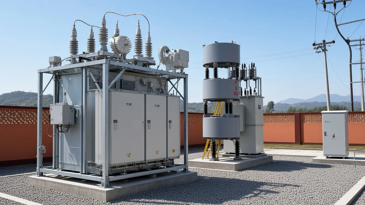
Where the Capacitor Bank Hangs on a 33/11 Single-Line
Many intake substations place the bank as a dedicated bay on the 11 kV main bus in parallel with outgoing feeders.
Walk the single-line from the 33 kV incoming bay through the power transformer to the 11 kV secondary. In a typical 33/11 kV injection substation the lower bus is the common point that feeds every outgoing 11 kV circuit, and that is where a station-mounted shunt capacitor bank usually taps in.
Utility programs that add HT shunt banks at 33/11 stations commonly install them on the 11 kV bus rather than on the high-side bushings. Commissioning write-ups for station-mounted reactive packages describe the same feed: supply from the 11 kV main bus, connected in parallel with the other 11 kV feeders, so the bay sits beside feeder switchgear instead of floating as a separate feeder-pole job.
Call that package an 11 kV bus capacitor bank when you mark the corrected node on the drawing. The bay still needs its own isolator, switching device, and protection—exactly the accessories other yard bays carry—so the reader should expect a feeder-like cubicle, not a bolt-on accessory on the transformer tank.
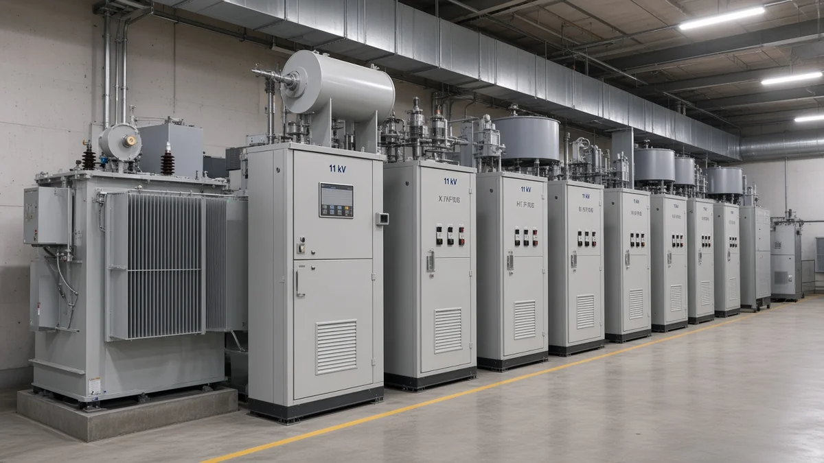
When the single-line shows the bank on the 33 kV bus / primary instead, treat that as a deliberate high-side choice driven by metering or high-side var need, not as the default intake pattern. The next section decides which of those two buses the project actually needs to correct.
Why the Corrected Bus Must Match the Meter or PCC
Correcting the 33 kV primary does not by itself fix PF measured on the 11 kV secondary—put the bank on the bus whose reading must improve.
Primary vs secondary capacitor bank placement is a measurement decision. The bank supplies leading vars only at the bus where it is connected; vars injected on the high side of the power transformer do not rewrite the PF or demand reading taken on the low-side bus.
An industrial buyer who meters PF on the 11 kV intake but quotes a bank on the 33 kV primary will watch the secondary meter stay lagging while the high-side bus looks “corrected.” The mismatch is electrical, not contractual: the metering / PCC point defines which bus must move.
| Decision cue | Prefer 11 kV secondary bus | Prefer 33 kV primary / HT side |
|---|---|---|
| Meter or PCC that must improve | Secondary / 11 kV intake reading | High-side metering or transmission-side var need |
| Feeder proximity | Bank sits beside outgoing 11 kV feeders | High-side bay; feeders stay on the transformer secondary |
| Typical 33/11 intake practice | Common in utility 33/11 programs | Used when high-side vars or billing point require it |
| Cost / insulation class | Lower equipment voltage class on the secondary | Higher class gear on the primary |
Important: Power factor correction on the 33 kV primary does not improve the power factor measured on the 11 kV secondary — put the bank on the bus whose PF or voltage reading actually has to move.
If the utility invoice or plant SCADA point sits on the 11 kV bus, keep the bank there even when a catalog sheet talks about “33 kV class” hardware. Hardware voltage rating and corrected-bus voltage are related purchase inputs; they are not interchangeable labels for the same node.
What Intake-Substation Duty Asks of the Bank at This Class
At this class the bank supplies local leading vars and voltage support at the corrected bus; general purpose detail hands off to the live WHY article in one sentence.
33/11 kV substation reactive compensation at intake is a local reactive job. Inductive feeders and plant load pull lagging vars; the shunt bank supplies leading reactive power at the chosen MV bus so that reactive share does not ride all the way from remote sources.
Switched banks track heavy load and drop steps at light load so leading PF and bus voltage rise stay off the night curve. Fixed banks still appear where the reactive profile barely moves, but intake substations usually see a day/night shape that argues for stepping.
For the broader stack of voltage support, PF, losses, and capacity release that every substation bank can serve, use the live WHY sibling on substation capacitor-bank purpose—this page stays on where the 33/11 bay sits and what that placement forces at order time.
Field Cues: Substation Bay Versus Plant MCC or Pole Rack
Outdoor frame/box or indoor bay, switched groups, and bay-coordinated protection mark station equipment—not a feeder pole rack or plant MCC cabinet.
Stand in the yard and look for a dedicated bay: outdoor frame or weatherproof box, bushings or cable entries, isolator and switching device in series with the capacitor groups, and often a series reactor (damping reactor) ahead of the cans. Indoor versions sit as a metalclad cubicle on the same switchgear line-up as the feeders.
Unbalance protection belongs with that bay language. Distribution and transmission banks are commonly wye-connected, and neutral CT or double-star schemes watch for a failed unit by seeing the bank go lopsided—equipment you will not find on a three-phase pole rack bolted to a wood pole.
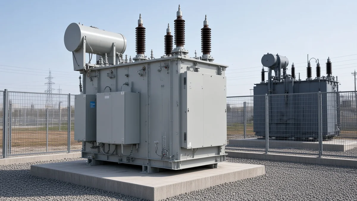
From the field: When the capacitors sit on the distribution bus inside the substation, the relays that watch the low-side transformer breaker are programmed so a step-in is not treated as a fault — that bay coordination language is how crews separate station banks from feeder-pole banks.
A plant MCC cabinet hanging LV automatic power-factor correction behind a process board is a different purchase altogether. So is a pole-mounted distribution bank out on a long feeder; both can be capacitors, but neither is the outdoor yard package this 33/11 placement case is describing.
Fixed Versus Automatic Stepping Under Daily Intake Load
Daily reactive shape at intake substations usually needs stepped/automatic switching so light-load leading is avoided.
Night load on an intake bus often drops while a fixed bank stays online. The surplus leading vars push PF toward leading and can raise bus voltage—exactly the light-load risk switched shunt practice is meant to avoid.
APFC / automatic stepping adds and drops capacitor groups as the intake reactive profile moves through the day. Controllers may key on voltage, power factor, time, or current; the buyer decision at this class is whether the daily Q shape is flat enough for a fixed block or needs a stepped outdoor yard package.
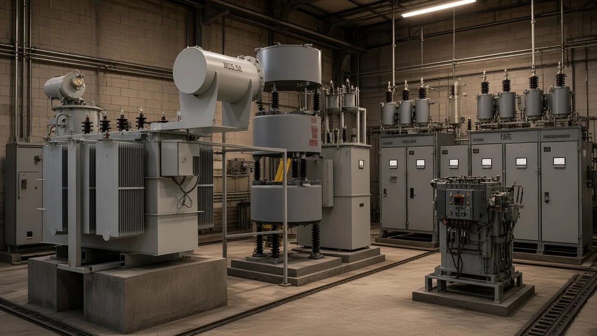
Fixed banks still fit steady industrial base load with little overnight swing. For most utility 33/11 intake duties, treat automatic stepping as the default architecture cue and reserve fixed blocks for a measured flat profile—not for hope that night load will stay high.
Order Inputs That Are Special Because of This Placement
Lock corrected-bus voltage, daily Q profile, bus short-circuit context, feeder harmonic exposure, outdoor envelope, and bay protection coordination—no worked kvar essay.
Placement turns ordinary purchase fields into bay-specific traps. The corrected-bus voltage is the system voltage on the bus the bank actually connects to; it is not a nearest catalog nickname copied from a 6/10/35 kV product list onto an 11 kV or 33 kV single-line.
| Order input | Why this placement makes it matter | What the buyer writes down |
|---|---|---|
| Corrected-bus voltage | Bank connects to one bus on the 33/11 single-line | Actual kV on that bus (11 or 33 class as drawn)—not “nearest” catalog class |
| Daily reactive profile | Intake load shape drives fixed vs automatic stepping | Peak/light Q pattern or “needs APFC steps” |
| Bus short-circuit context | Bay switching and inrush sit on that bus’s fault level | Available fault level or study reference at the corrected bus |
| Feeder harmonic exposure | Downstream feeders can push harmonics into the bank | Harmonic note or “reactor / detuning required” |
| Outdoor environmental envelope | Yard package sees weather, pollution, and clearances | Indoor room vs outdoor box/frame; site ambient envelope |
| Bay protection coordination | Unbalance, OV, and breaker settings travel with the bay | Protection scheme note with the switching device |
Tip: Write the RFQ voltage as the actual corrected-bus voltage on the single-line — product pages that list 6/10/35 kV substation busbars are naming catalog classes, not declaring that 11 kV equals 10 kV or that 33 kV equals 35 kV as a standards identity.
Leave full kvar arithmetic and the general design decision sequence to the sizing and design siblings. This checklist only locks the inputs that exist because the bank is a 33/11 substation bay rather than a plant MCC or pole rack.
Which Substation MV Bus Package Fits This Placement: HYTBBT
HYTBBT is marketed for substation installation on listed MV bus classes; inquire with the actual corrected-bus voltage, not a catalog nickname.
When the single-line points to a substation MV bus under daily load shape—not a plant LV MCC and not a feeder pole—the HYTBBT Series On-load Voltage & Reactive Power Regulation System matches that duty language. The product overview places the system on 6–220 kV networks and states installation on 6 kV / 10 kV / 35 kV busbars in substations, with multi-stage capacitor compensation and automatic voltage plus reactive control, indoor or outdoor.
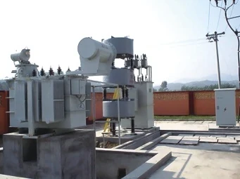
A 33/11 project that corrects the 11 kV secondary is nearest the page’s lower MV bus language; a project that must correct a 33 kV-class primary is nearest the page’s higher MV bus language. In either case the order still carries the real bus voltage from the drawing. Do not invent a standards identity between 11 and 10, or between 33 and 35, just to force a catalog match.
Skip this package when the job is really an LV plant MCC APFC cabinet, a pole-mounted feeder bank, or a site that still needs a full design calculation sequence before any SKU is named. After placement is clear, the high voltage power factor compensation series hub is the natural next browse, with corrected-bus voltage, daily reactive profile, short-circuit context, harmonic exposure, and indoor/outdoor preference stated in one soft enquiry sentence.
FAQ
How is a capacitor bank connected on the 33/11 kV buses?
Usually as a dedicated bay on the 11 kV main bus in parallel with outgoing feeders. Some projects put it on the 33 kV primary when that bus is the metering or high-side var point that must improve.
Why the 11 kV bus instead of the 33 kV bus?
Secondary-side compensation sits closer to the distribution feeders and often uses a lower equipment voltage class. Confirm the choice against the meter or PCC; if the reading that matters is on the primary, the bank has to follow that bus.
What is the purpose of the bank here?
Local leading reactive power and voltage support at the corrected bus so inductive feeders do not import that reactive share from remote sources. The general purpose stack—PF, losses, capacity—is covered in the substation capacitor-bank purpose article.
Fixed or automatic bank for this duty?
Intake substations usually see a daily reactive shape, so stepped or automatic switching is the safer default to avoid light-load leading. Use a fixed bank only when measured Q stays nearly flat across the day.
How do I recognize substation-bay equipment vs pole-mounted?
Look for an outdoor frame or box, or an indoor bay cubicle, with switched groups and bay-coordinated protection such as unbalance and overvoltage schemes. A feeder pole rack is a different hardware family.
What order inputs are special because of this placement?
Corrected-bus voltage, daily reactive profile, bus short-circuit context, feeder harmonic exposure, outdoor environmental envelope, and protection coordination with the bay. Those fields exist because the bank is station equipment on a chosen MV bus.
How to calculate kvar requirement?
You need measured kW/kVAR and the target at the same bus the bank will correct. This article does not run a worked kvar example; sizing depth belongs with the PF-correction and design siblings.
References
- IEEE Technology Navigator — Shunt Power Capacitors — local leading vars at the point of application; switched banks track load to avoid light-load leading PF.
- DOE — Voltage and Reactive Power — utility practice for fixed versus switched capacitors and voltage-support roles.
- SEL — Capacitor Bank Protection — wye bank arrangements and unbalance protection suited to the neutral scheme.
- Prepare.org preprint — HT shunt banks at 11 kV bus of 33/11 kV substations — utility intake placement practice on the 11 kV bus.
- Elliptical Focus — Commissioning capacitor banks in a 33/11 kV substation — station-mounted bank fed from the 11 kV main bus parallel to feeders.
- Reddit r/Lineman — Capacitor bank question — crew language separating distribution-bus banks inside the substation from feeder-pole banks, including relay programming when steps kick on.