
 Zhejiang Hongyan Electric Co., Ltd.





































Why do we use capacitor bank in substation applications? Because a shunt capacitor bank supplies leading reactive power locally so inductive feeders and loads do not pull that reactive share all the way from upstream generators and lines.
That local kvar supports bus voltage, improves power factor, cuts I²R losses, and frees transformer and cable capacity for real power. The sections below walk the purpose stack for a shunt capacitor bank in substation service, show capacitor bank voltage support and fixed vs switched capacitor bank control risk, and point to a packaged MV/HV cabinet when the job sits in a yard or indoor distribution room—not on a distribution pole.

Why Substations Install Shunt Capacitor Banks
Banks supply leading reactive power locally for inductive feeders and loads.
Most outgoing feeders from a distribution or industrial substation serve motors, transformers, and other inductive equipment. Those loads draw lagging reactive power. Without local compensation, that reactive current rides the upstream network, loading lines and transformers and dragging bus voltage and power factor with it.
A shunt capacitor bank sits in parallel on the bus. Capacitors supply leading vars that offset the lagging demand at the point of application. IEEE technology notes on shunt power capacitors describe the same mechanism: generate reactive power locally, reduce the reactive current that must flow from remote sources, and improve the power factor where the bank is applied. Educational power-system pages make the substation case explicit—when inductive feeders dominate, the bank is there to restore reactive balance on that bus.
If you need the object definition of a bank (units, switching, discharge paths), use the sister guide on what capacitor banks are. This page stays on why substations install them.
Capacitor Bank Voltage Support on the Substation Bus
They support bus voltage when lagging load would otherwise pull it down.
Reactive power and voltage travel together on AC networks. Under heavy lagging load, voltage at the substation bus and along feeders tends to sag. A shunt bank injects capacitive vars on that bus and raises voltage toward the operating band the utility or plant expects.
Utility voltage-and-reactive guidance treats capacitor banks as voltage-support tools that switch with load, while load-tap changers and regulators handle finer voltage steps. Independent education pages put voltage regulation first among substation reasons for shunt capacitors: load varies through the day, so a bus-connected bank is there when the lagging peak arrives.

A medium-voltage bank on a distribution bus is the same job in a common MV class: local kvar for that bus, not a different physics. Voltage class and kvar sizing still belong to project engineering; the purpose does not change with the nameplate kilovolts.
Power Factor Improvement at the Substation
They offset lagging reactive demand so measured power factor rises.
Power factor is the ratio of real power to apparent power. When reactive current is large, apparent power rises and power factor falls even if the useful kilowatts stay the same. A shunt bank reduces the reactive share that the metering point sees, so power factor moves closer to the target the utility or internal standard sets.
Industrial sites often face utility thresholds around 0.90 or 0.95 lagging; below that, demand or PF charges appear. Substation placement matters because the bank corrects the bus that actually feeds those inductive loads. For operating benefits framed around industrial PFC generally, see what capacitor banks do and the buyer guide on a capacitor bank for power factor correction—this article does not re-own kvar formulas.
How Capacitor Banks Reduce I²R Losses
Less reactive current through feeders and transformers means lower I²R losses.
Current in a conductor produces heating losses that scale with the square of current. Reactive current does not deliver net work at the load, but it still flows and still heats cables, buswork, and transformer windings. When a bank supplies that reactive share locally, upstream current falls and those I²R losses fall with it.
Field discussions among electricians make the same point in plain language: reactive current loads transmission and distribution assets and raises line losses, which is why utilities place switched banks where load varies. The loss benefit is real only to the extent reactive flow through those assets actually drops—another reason placement and step control matter.

Capacity Release and Substation Economics
Freeing thermal capacity and cutting losses—plus avoiding poor-PF charges where tariffs apply—is the business case.
Transformers, cables, and switchgear are sized on apparent power and thermal limits. When they also carry large reactive current, less headroom remains for real load. Shunt compensation reduces that reactive loading so the same assets can deliver more useful kilowatts without an immediate upgrade.
| Purpose | What the bank changes | Why substations care |
|---|---|---|
| Local reactive supply | Leading kvar at the bus | Inductive feeders stop importing that reactive share |
| Voltage support | Bus voltage under heavy lagging load | Keeps the bus inside operating limits |
| Power factor | Measured PF at the application point | Meets utility or plant PF targets |
| Loss reduction | Lower current through upstream paths | Cuts I²R heating in lines and transformers |
| Capacity release | Lower reactive share of loading | Defers transformer/cable upgrades |
On the utility side, lower losses and deferred capital are the usual economic story. On the industrial side, the same physics shows up as avoided PF penalties and more usable transformer capacity. Neither story requires inventing site-specific savings numbers—the decision is still driven by measured load, voltage, and tariff rules for that project.
Fixed vs Switched Capacitor Banks in Substations
Switched banks follow load so light-load leading power factor is less likely.
A fixed bank stays connected. It is simple and fits relatively steady reactive demand. A switched (often automatic) bank adds and removes capacitor steps using time, voltage, power factor, or current signals. Utility and education sources treat switching as normal practice because daily load curves swing hard: evening peaks need vars; overnight valleys often do not.
Important: Leaving too much capacitance online at light load can push a leading power factor and raise voltage. Practitioners warn that oversized or always-on banks create leading-PF conditions and extra losses when the power factor is not near unity—so step control belongs in the purpose discussion, not only in a commissioning checklist.

| Mode | Best when | Watch-outs |
|---|---|---|
| Fixed bank | Reactive demand is fairly steady | Light-load leading PF and voltage rise |
| Switched / automatic steps | Load and voltage vary through the day | Switch duty, control settings, step size |
| Packaged MV/HV cabinet | Indoor room or outdoor substation yard needs a coordinated bank | Harmonics may need series reactors; pole-line jobs differ |
Pole-mounted banks solve feeder-end voltage and loss problems on outdoor lines. That is a different placement job from a substation yard or indoor MV room package, and it is owned by a separate article in this cluster—not here.
Recommended MV/HV Package: HYTBB Compensation Cabinet
A packaged HYTBB cabinet in the published medium- and high-voltage range matches yard and indoor substation shunt jobs.
When the decision is a medium- or high-voltage shunt bank in a substation or distribution room, look at the HYTBB Medium and High Voltage Reactive Power Compensation Cabinet. The live product description frames it as a shunt capacitor bank for power-frequency systems from 1 kV to 35 kV that compensates inductive reactive power to improve power factor, enhance voltage stability, reduce energy losses, and increase effective equipment capacity.
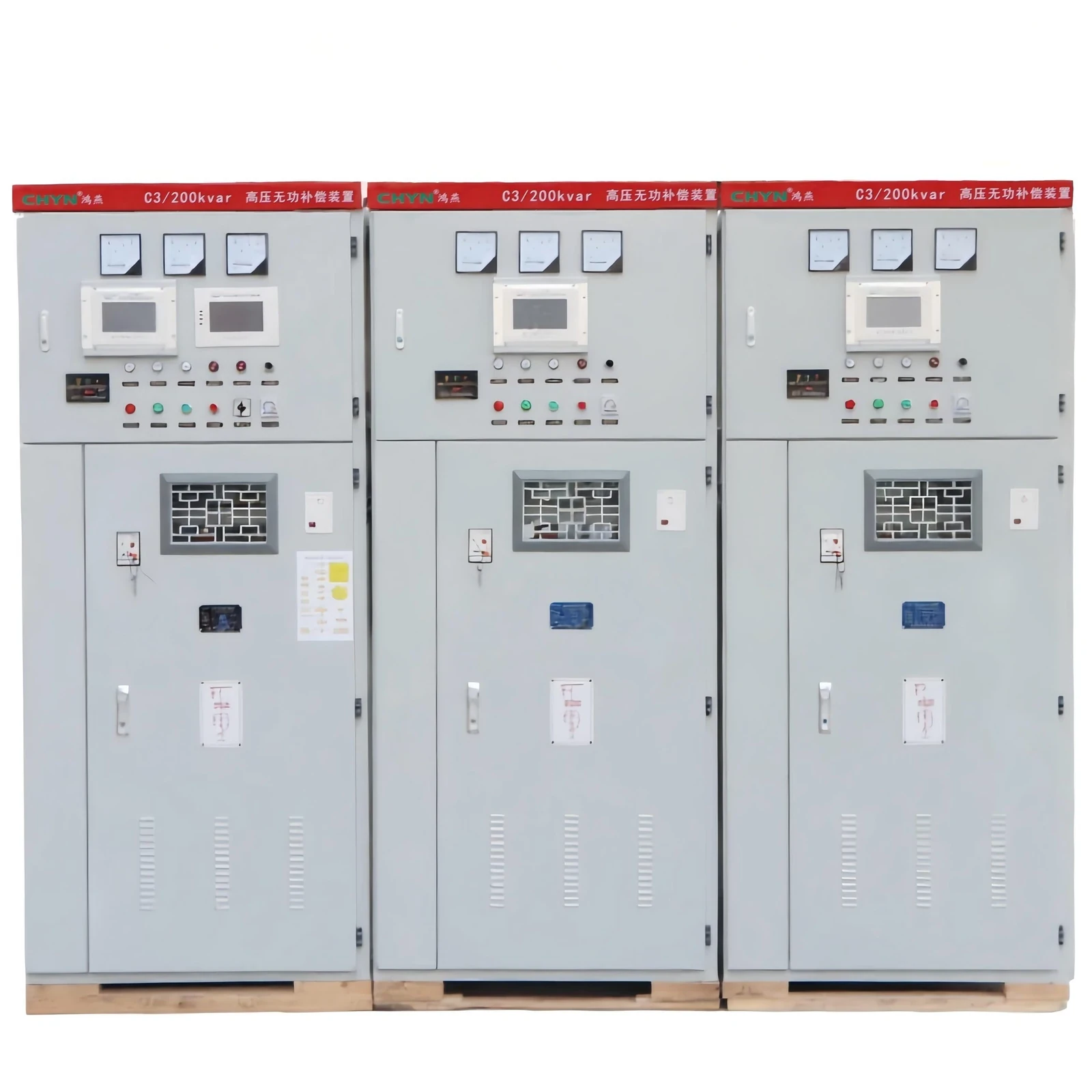
Published performance statements on that page include improving system power factor up to 0.95 or higher and reducing line current by about 10–20%. Series reactors are used to limit inrush and help with harmonics, and a discharge path is aimed at bringing residual voltage below 50 V within minutes after disconnection. Switching can be fixed or configured for manual or automatic group control. Rated capacity on the technical table spans 50–20,000 kvar at 10(6)–35 kV class entries.
Related live packages in the same high-voltage power factor compensation series cover outdoor box, indoor frame, and outdoor frame layouts for substations and industrial distribution rooms. Choose those when the civil and enclosure layout demands a frame or outdoor box rather than a switchgear-integrated cabinet. Do not treat a pole-mounted device as the default answer for this substation WHY query.
FAQ
What is the purpose of a medium-voltage capacitor bank in a substation?
The same purpose stack on an MV bus: supply local leading kvar, support bus voltage, improve power factor, cut upstream I²R losses, and free transformer capacity. The medium-voltage label is a voltage class, not a different reason for installing the bank.
What are the risks of using capacitor banks?
The main operational risks are light-load leading power factor and voltage rise if too much capacitance stays online, switching duty on breakers or contactors, and harmonic interaction or resonance when the network is distorted. Series reactors and proper step control are the usual engineering responses.
Why do manufacturers and plants use capacitor banks?
Plants use them for the same physics—PF targets, voltage support near inductive loads, loss and capacity relief—often under utility PF billing. Substation banks may sit on the utility or industrial MV bus that feeds those plants; the placement differs, the reactive purpose does not.
What are the two types of capacitor banks that matter for this topic?
For substation purpose and control, think fixed versus switched (automatic) banks. Connection schemes and enclosure styles matter for design, but the control mode is what decides whether light-load leading PF becomes a nightly problem.
Why not leave a capacitor bank connected all the time?
Because load falls at night or between shifts. A bank sized for peak lagging load can overcompensate at light load, driving leading power factor and higher voltage. Automatic switching or timed steps exist for that reason.
Do series reactors always come with a substation bank?
Not always, but packaged MV/HV cabinets often include them to limit energization inrush and shape harmonic behavior. Reactor percentage is a project choice tied to voltage class and harmonic conditions—see the HYTBB product data for the published typical ranges on that cabinet.
Is a pole-mounted bank the same as a substation bank?
No. Pole-mounted units target feeder voltage and losses on outdoor lines. Substation packages sit on the bus or in a distribution room. Keep those buying paths separate.
When does a packaged HYTBB cabinet fit?
When you need a packaged shunt compensation cabinet for indoor or outdoor substation-style duty with fixed or group switching, optional reactors, and switchgear-oriented integration across the HYTBB published voltage range. Fast, highly fluctuating loads may need dynamic TSC/SVG-class equipment instead.
References
- Shunt Power Capacitors — IEEE Technology Navigator
- Application of Automated Controls for Voltage and Reactive Power Management — Department of Energy
- Shunt Reactive Power Compensation — Top10Electrical
- Why shunt capacitor bank used in the substation? — Electrical Desks
- Power Factor — Electrician Talk forum thread