
 Zhejiang Hongyan Electric Co., Ltd.






































Define active power and reactive power by separating useful work from field exchange. Active (real) power is the average net energy that does work, measured in watts. Reactive power is the oscillating exchange with magnetic and electric fields, measured in var.
Both sit with apparent power on the power triangle that plant meters and HV capacitor decisions depend on.
This page is an active and reactive power definition for AC systems—not a full power-factor essay and not a calculation worksheet. You will see units, the triangle with apparent power, the difference between active and reactive power, why reactive vars still matter for voltage and feeder loading, and when an outdoor HV shunt bank is a logical next step. For computation steps, use the live how to calculate reactive power guide after the definitions are clear.
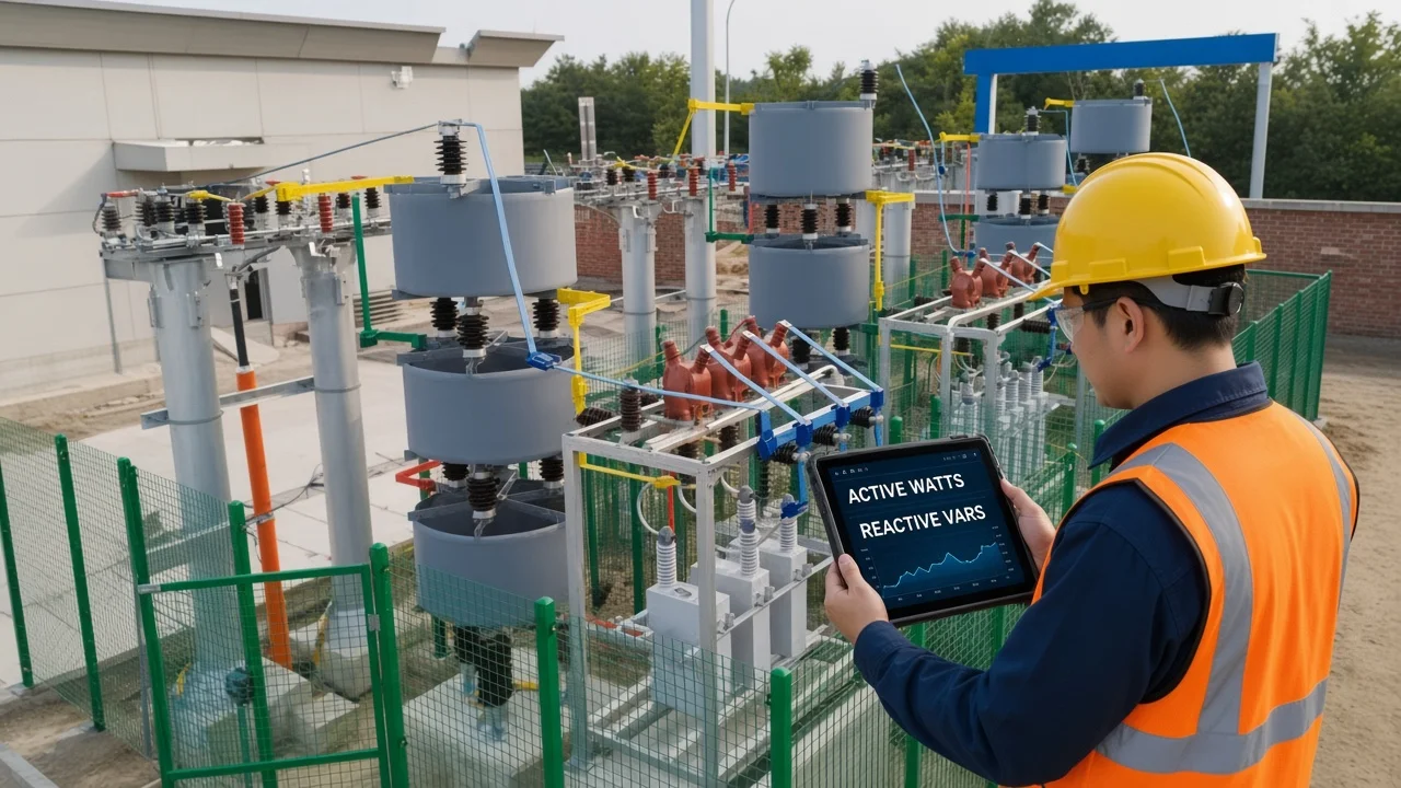
What Active (Real) Power Means
Active power is average net energy that does work, measured in watts. Engineers also call it real power or true power.
In sinusoidal AC, average power delivered by a source is P = Vrms × Irms × cos φ, where φ is the phase angle between voltage and current (OpenStax University Physics on AC power; Wikipedia AC power). That average is the energy that leaves the source and does not return as net transfer over a cycle.
On a plant floor, active power is what turns shafts, heats elements, and lights lamps. Kilowatt-hour meters track this useful energy. When you ask what is active power and reactive power, start here: watts are the work channel.
Resistive loads consume active power. Ideal inductors and capacitors do not add to that average—they belong on the reactive side of the story.
What Reactive Power Means
Reactive power is oscillating field exchange with zero average, measured in var. It is the amplitude of energy that moves into magnetic or electric storage and back out each cycle.
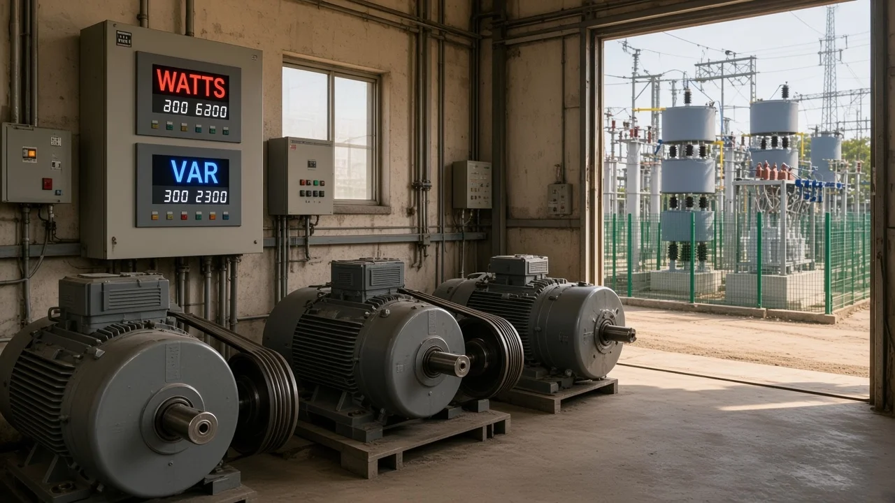
Power-system teaching writes complex power as P + jQ and uses different units on purpose: watts for real power, volt-amperes-reactive (VAR) for reactive power, and volt-amperes (VA) for apparent power (LibreTexts Energy and Power). Instantaneous power can be rewritten so the Q term exchanges energy with zero average.
Ideal inductors and capacitors absorb energy for part of a cycle and return it for the rest, so their average power is zero (OpenStax). Motors and transformers still need that magnetizing exchange to build flux. The exchange is not “wasted heat,” but the current that carries it still occupies conductors.
Power Triangle: How Active, Reactive, and Apparent Power Fit
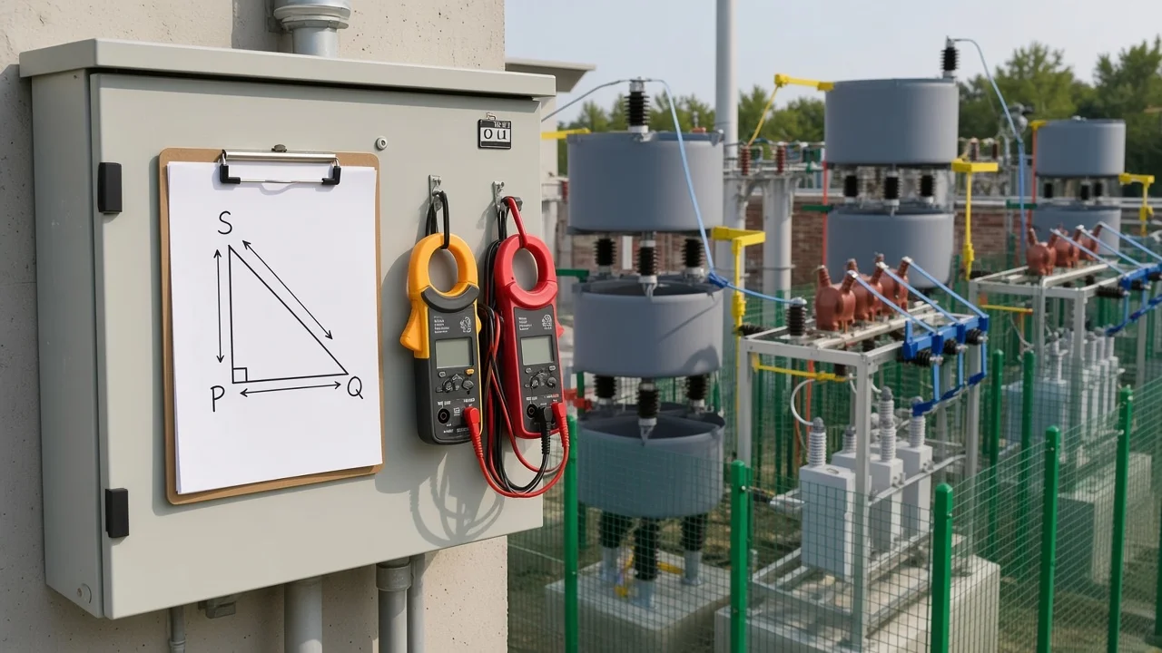
S is the hypotenuse of P and Q; S² = P² + Q². Apparent power is the VA magnitude the source and feeders must supply.
For sinusoidal voltage and current, independent formula sheets state P = Vrms Irms cos φ, Q = Vrms Irms sin φ, and S = Vrms Irms, with complex power S̃ = P + jQ (Atlas of Engineering AC power formula sheet). The same geometry appears as a right triangle: P on the horizontal axis, Q on the vertical axis, and S as the hypotenuse (Wikipedia AC power).
| Quantity | Symbol | Common unit | Sinusoidal identity |
|---|---|---|---|
| Active (real) power | P | W, kW | P = Vrms Irms cos φ |
| Reactive power | Q | var, kvar | Q = Vrms Irms sin φ |
| Apparent power | S | VA, kVA | S = Vrms Irms = √(P² + Q²) |
A common load convention treats positive Q as inductive (lagging current) and capacitive vars as the opposite sign (Atlas formula sheet). State the convention before you add signed banks on a bus.
Educational illustration from LibreTexts: a sample network can show P = 144 W and Q = 144 VAR at a 45° power-factor angle—equal legs on the triangle when φ = 45° (LibreTexts Energy and Power). Treat that as teaching arithmetic, not a measured plant log.
Difference Between Active and Reactive Power
Active does work; reactive sustains fields and still loads conductors. That is the practical difference between active and reactive power procurement and operations teams need.
| Topic | Active power (P) | Reactive power (Q) |
|---|---|---|
| Physical role | Net energy that does useful work | Energy exchange with L/C fields |
| Average over a cycle | Non-zero when the load does work | Zero net energy for ideal L/C |
| Unit | Watt (W) | Volt-ampere reactive (var) |
| Plant language | Working kW | Magnetizing / field kvar |
| Meter implication | Energy billing basis | Raises VA and conductor current |
OER teaching puts the same contrast in energy-flow language: real power leaves and does not return; reactive energy oscillates quarter-cycle by quarter-cycle yet still occupies conductor and transformer capacity (OERTX AC circuit analysis context).
If a new engineer hears “reactive power is useless,” correct the framing. It does no net work at the load, but it is not free to ignore on feeders.
Forum threads still remind beginners that V × I on a clamp meter is apparent power in VA, while real watts need a true power measurement (EEVblog electronics math and power factor thread). For RL-circuit physical meaning in more depth, see what reactive power represents in an AC RL circuit.
Why Reactive Power Matters for Voltage and HV Compensation
Q still loads feeders and shapes voltage support; local capacitors supply vars. Definitions alone do not size a bank, but they explain why compensation exists.
Reactive current raises apparent power for a given kilowatt load. Transformers, cables, and switchgear must be sized for the VA that includes those vars. That is why industrial customers and utilities care about Q even when energy meters show only kilowatt-hours.
On distribution and plant buses, shunt capacitors supply local capacitive vars so less reactive current travels upstream (OSTI power-triangle refresher framing; community language that capacitors keep reactive exchange in a tighter loop). Local vars also support voltage when inductive loads pull the bus down.
Important: Reactive energy oscillates without being consumed as net work, but it still occupies conductor and transformer capacity — source: OERTX AC circuit analysis teaching and community language that reactive current still loads wires. High kvar on a feeder can look “quiet” on a kilowatt meter while amp loading and voltage support remain stressed.
Line-flow behavior of P and Q on transmission paths is a separate topic—see active and reactive power flow in a transmission line after these definitions. For balanced three-phase Q formulas, use reactive power formula in 3 phase rather than retelling that worksheet here.
Power Factor Bridge Without a Full PF Essay
PF = P/S; deeper PF definition lives on the sibling page. Power factor is the ratio of active power to apparent power, and for sinusoidal waveforms it equals cos φ (Atlas formula sheet; OpenStax).
A lower PF means a larger share of S is reactive for the same P. That is useful context when you later compute Q from P and PF, but this article does not replace a full “power factor in electrical engineering” definition essay. Keep the bridge short: once you can define P and Q, PF is simply how much of the VA triangle is real work.
When you need numbers, move to how to calculate reactive power with simultaneous meter readings.
Which HYTBB Fit After You Can Define Active and Reactive Power
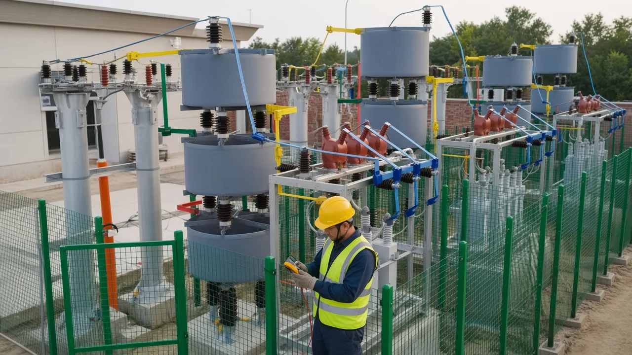
MV/HV shunt banks are selected from required kvar and voltage class. After inductive Q is understood as magnetizing demand, an outdoor-frame high-voltage capacitor package is a common plant next step—not a substitute for the definitions above.
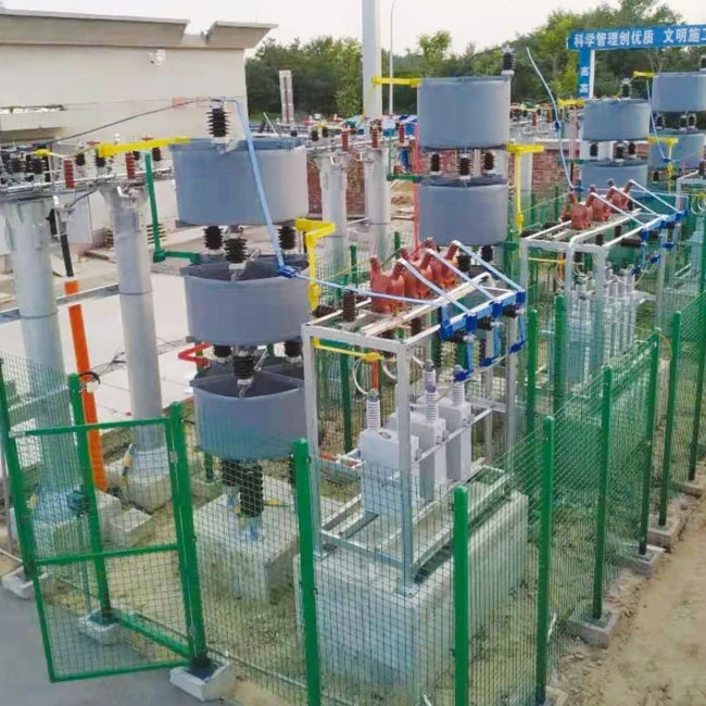
When inductive Q is the problem you must offset, the HYTBB Series High-Voltage Reactive Power Compensation Device – Outdoor Frame Type is the outdoor-frame HV shunt package on this site. Choose reactor ratio, protection style, connection form, and fixed versus automatic switching from the bus voltage, harmonic environment, and the kvar you need.
Printed nameplate windows cover 6–35 kV and 50–60 Hz. Catalog capacity spans 150–10,000 kvar on 10 kV and below, and 600–20,000 kvar at 35 kV. Individual can ratings are listed from 50–500 kvar.
| Published selection item | Printed range / note |
|---|---|
| System voltage | 6–35 kV |
| Frequency | 50–60 Hz |
| Rated capacity (≤10 kV) | 150–10,000 kvar |
| Rated capacity (35 kV) | 600–20,000 kvar |
| Single capacitor unit | 50–500 kvar |
Browse the high-voltage power factor compensation series when you need the wider family. Fast-swinging impact loads may need dynamic options such as HYTSC / HYSVC on that same hub—definitions of P and Q do not by themselves finish a Qc design.
FAQ
What is the definition of active power and reactive power?
Active (real) power is the average net energy that does useful work, measured in watts. Reactive power is the oscillating exchange with magnetic and electric fields each cycle, measured in var, with zero net energy transfer for ideal storage elements.
What is the difference between active and reactive power?
Active power performs work and shows up as kilowatts. Reactive power sustains fields and returns energy each cycle, yet the current that carries it still loads conductors and transformers.
What units are used for active, reactive, and apparent power?
Use watts (W) for active power, volt-amperes reactive (var) for reactive power, and volt-amperes (VA) for apparent power. Plant boards often show kW, kvar, and kVA.
How do active and reactive power relate on the power triangle?
On the power triangle, P and Q are the legs and S is the hypotenuse: S² = P² + Q². For sinusoids, P = S cos φ and Q = S sin φ.
Why does reactive power matter if it does no net work?
Because reactive current still raises apparent power and occupies feeder and transformer capacity. Local capacitors supply capacitive vars so less reactive current travels upstream and voltage support improves.
Does reactive power mean wasted energy?
No. Ideal reactive exchange is not net consumption. Calling it “wattless” only means no average work—not that the current is free to ignore on wires and transformers.
How is power factor related to active and reactive power?
Power factor is P/S. For sinusoidal waveforms it equals cos φ. A full PF-in-electrical-engineering essay is out of scope here; use this page for P and Q definitions first.
After I understand P and Q, what is the next step for HV compensation?
Compute required kvar from simultaneous plant readings, then compare system voltage and capacity needs to an HV shunt package such as the HYTBB outdoor frame. Use the calculation sibling for formulas and the HV hub for the product family.
References
- AC power — Wikipedia
- Energy and Power — Engineering LibreTexts (Kirtley)
- 15.4 Power in an AC Circuit — OpenStax University Physics Volume 2
- AC Power Formula Sheet — Atlas of Engineering
- Electronics Math and Power Factor Not Adding Up — EEVblog Forum
Humanizer self-audit (Draft Agent CHYN-DFT-DAP-20261029-01): second pass removed stacked rhetorical questions, kept educational examples labeled, avoided claim-ID leakage, varied paragraph length, and kept product proof limited to printed HYTBB ranges. No invented UL/NEC/SKU/savings claims.