
 Zhejiang Hongyan Electric Co., Ltd.






































what does reactive power represent in an ac rl circuit is magnetic-field energy the inductor stores and returns to the source each cycle—not net watts burned in the coil. The resistor still dissipates active power as heat or work. Later sections separate those roles, connect phase angle and lagging power factor, contrast R-only and RC cases, show labeled educational arithmetic, and show when inductive reactive power on a plant bus calls for a shunt capacitor.
If you only need what is reactive power in ac circuit in one line: it is the quadrature exchange with inductance or capacitance. In an RL load, that exchange is inductive.
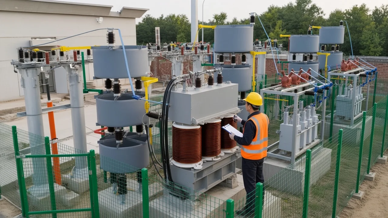
What Reactive Power Represents in an AC RL Circuit
Q is magnetic-field energy stored and returned by the inductor each cycle. In a series RL path, the inductor builds a magnetic field while current rises and collapses that field later in the AC cycle, sending energy back toward the source (OpenStax University Physics on power in an AC circuit).
An ideal inductor’s average real power is zero. University physics states the same limit for a pure inductor or capacitor: average power over a cycle is zero because energy absorbed in one half-cycle is returned in the other (OpenStax University Physics on power in an AC circuit). Laboratory teaching materials say the same in engineering units: real power (watts) lives in the resistance, while reactive power (var) belongs to the reactive element that stores and releases energy (Analog Devices StudentZone lab on AC power and power factor).
Reactive power uses the unit volt-ampere reactive (VAR, kvar, Mvar). That name exists so operators do not confuse cycling field energy with kilowatt-hours that do work or become heat.
Active Power vs Reactive Power in RL Loads
Watts stay with the resistive part of the RL load; Q cycles in the inductance but still drives ampere loading. Active power is the average rate of energy converted to heat, light, or mechanical work. In an RL series circuit, that average sits in R.
Reactive power is the rate associated with energy moving into and out of the magnetic field. Encyclopedia AC-power pages keep Q as the quadrature leg of complex power: Q equals |S| sin φ, and |S| = √(P² + Q²) (Wikipedia article on AC power).
Independent tutorials write Q = V I sin Φ in VAR and place P, Q, and S on a power triangle (Electronics Tutorials reactive power page). Practitioner forum threads make the same split in bench language: V × I is volt-amperes, a wattmeter reading is watts, and power factor is P/S (EEVblog forum thread on electronics math and power factor). Reactive power does not bill as kWh the same way watts do, yet the ampere loading is real.
Lines, transformers, and switchgear must carry the current that supports Q even when average net energy transfer in the inductor is zero (IEEE Technology Navigator topic on reactive power).
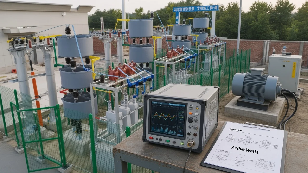
Phase Angle, Lagging PF, and the Power Triangle
An RL circuit draws lagging current; power factor is cos φ. Inductance resists change in current, so the current waveform sits behind the voltage waveform. For sinusoidal conditions, Q equals V I sin φ, or I² times inductive reactance X_L (IEEE Technology Navigator topic on reactive power; Analog Devices StudentZone lab on AC power and power factor).
Power factor is P / S. On a clean sine wave that equals cos φ. When X_L is nonzero, the phase angle sits between 0° and 90° and PF is less than 1.
The power triangle’s vertical leg is then inductive Q. Lab materials call that lagging power factor because load current lags load voltage (Analog Devices StudentZone lab on AC power and power factor).
Under the common load convention used in IEEE topic summaries, inductive reactive power is positive and capacitive reactive power is negative (IEEE Technology Navigator topic on reactive power). Sign language matters later when a capacitor bank cancels inductive Q.
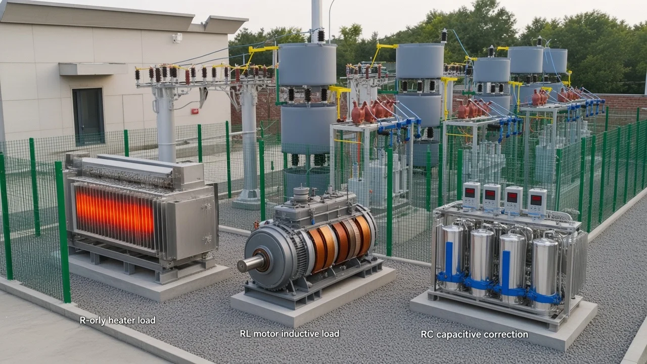
R-Only vs RL vs RC — What Changes
A pure resistor carries almost no reactive power; a pure inductor carries almost no average watts. Add capacitance and the sign of Q flips relative to the inductive case.
| Circuit | Phase relationship | Real power | Reactive power (usual load convention) |
|---|---|---|---|
| R-only | Voltage and current in phase (φ ≈ 0°) | P ≈ S; all watts | Q ≈ 0 |
| RL (inductive) | Current lags voltage | P = I² R (or V I cos φ) | +Q inductive; Q = I² X_L or V I sin φ |
| RC (capacitive) | Current leads voltage | P in the resistance | −Q capacitive (opposite to inductive) |
| RLC | Net reactance X_L − X_C | Still only in R | Q follows the net reactance |
Independent tutorials note that motors, generators, and transformers consume reactive power to sustain magnetic fields, while capacitors are the usual industrial tool for offsetting lagging demand (Electronics Tutorials reactive power page). Wikipedia’s AC-power overview uses the same directional language: inductors absorb Q and capacitors generate Q under the common convention (Wikipedia article on AC power).
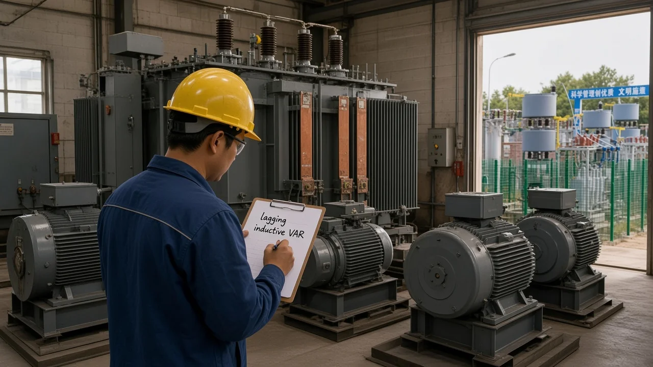
Plant Meaning — Magnetizing VAR, Not Wasted Watts
Magnetizing VAR is required for motors and transformers to build their magnetic fields. Calling that VAR “wasted energy” hides two facts at once: the field is necessary for the machine to work, and the ampere path still loads feeders and transformers (Electronics Tutorials reactive power page; IEEE Technology Navigator topic on reactive power).
Plant language often treats an induction-motor feeder as an RL-type load: shaft work and copper/core losses show up as kilowatts, while magnetizing and leakage reactance show up as lagging kvar. The board may report a lagging power factor even when the process is doing useful mechanical work.
Important: Reactive power is not a pile of discarded kilowatt-hours sitting in the inductor. It is cycling field energy. The operating cost shows up as higher current for the same real power—larger conductor heating, transformer loading, and, for many industrial tariffs, a power-factor or kvar charge (IEEE Technology Navigator topic on reactive power).
A shunt capacitor supplies leading Q that offsets lagging RL demand. Teaching labs correct a series RL load by paralleling capacitance so voltage and current move back toward in-phase operation (Analog Devices StudentZone lab on AC power and power factor). Industrial practice scales that idea to bus-level capacitor banks and dynamic compensators on the High Voltage Power Factor Compensation Series.
Worked RL Examples (Labeled Educational)
Run stated-input P/Q/S and I²X_L examples without inventing plant logs. The numbers below are worked arithmetic from declared inputs, not measured readings from a named site.
| Example | Stated inputs | Path | Result |
|---|---|---|---|
| A | V = 120 V rms, I = 2 A rms, φ = 30° | P = V I cos φ; Q = V I sin φ; S = V I | P ≈ 207.8 W; Q = 120 VAR; S = 240 VA |
| B | I = 5 A rms, X_L = 30 Ω | Q = I² X_L | Q = 750 VAR |
Example A uses the sinusoidal identities Q = V I sin φ and P = V I cos φ (IEEE Technology Navigator topic on reactive power; OpenStax University Physics on power in an AC circuit). Check: cos 30° ≈ 0.866, so P ≈ 120 × 2 × 0.866 ≈ 207.8 W; sin 30° = 0.5, so Q = 120 × 2 × 0.5 = 120 VAR; S = 120 × 2 = 240 VA; and √(P² + Q²) ≈ 240 VA.
Example B uses Q = I² X_L for the inductive branch (Analog Devices StudentZone lab on AC power and power factor). With 5 A through 30 Ω of X_L, Q = 25 × 30 = 750 VAR. Average watts in an ideal inductor remain zero; any real coil resistance would add a separate I²R term.
For three-phase meter paths that already assume line-to-line volts and √3, use the dedicated walkthrough on reactive power formula in 3 phase instead of stretching these single-path identities.
Which HYTBB Fit After You Understand RL Reactive Power
A shunt capacitor supplies leading Q that offsets lagging RL demand. Once inductive VAR is understood—and a required capacity is known—medium- and high-voltage projects often look at fixed or automatically switched shunt banks on the HV power-factor family.
When inductive demand is steady on a medium- or high-voltage bus, the HYTBB Series High-Voltage Reactive Power Compensation Device – Outdoor Frame Type provides outdoor-frame shunt capacitor compensation in the printed 6–35 kV class. Published ratings include 150–10,000 kvar at 10 kV and below, 600–20,000 kvar at 35 kV, 50–60 Hz operation, and single capacitor units from 50–500 kvar. Reactor ratio, protection method, connection form, and fixed or automatic switching are chosen from system voltage, harmonic conditions, and required capacity.
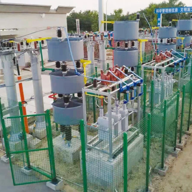
Fast-swinging mills, hoists, and similar impact loads may need dynamic options on the same hub (TSC / SVC-style equipment) rather than a slow stepped bank alone. Required capacitor kvar to hit a target power factor is a separate calculation after present Q is known—see how to calculate kvar for capacitor bank. This page stops at meaning and the first hardware fork; it does not invent savings percentages, payback, or listing claims.
FAQ
What does reactive power represent in an AC RL circuit?
Magnetic-field energy the inductor stores and returns each AC cycle. It is not net watts burned in an ideal coil (OpenStax University Physics on power in an AC circuit).
What is reactive power in an AC circuit?
The quadrature component that oscillates with inductance or capacitance, measured in VAR. Real power does work or becomes heat; reactive power sustains fields and still loads conductors (Wikipedia article on AC power; IEEE Technology Navigator topic on reactive power).
Is reactive power the same as wasted energy?
No. The energy cycles rather than disappearing as heat in an ideal inductor, but the current still stresses wiring and transformers. Motors and transformers also need inductive VAR to magnetize (Electronics Tutorials reactive power page).
How is reactive power different from active power in an RL circuit?
Active power averages in the resistance (watts). Reactive power belongs to the inductor’s reactance (VAR). Apparent power is the VA combination on the power triangle (Electronics Tutorials reactive power page).
Why does an RL circuit have a lagging power factor?
Inductance makes current lag voltage. Power factor equals cos φ on a sine wave, so a nonzero lagging φ yields PF below unity (Analog Devices StudentZone lab on AC power and power factor).
How do you calculate Q in a simple RL circuit?
For sinusoidal conditions use Q = V I sin φ or Q = I² X_L. The educational table above walks both forms with stated inputs. Three-phase line-value formulas belong on the reactive power formula in 3 phase page.
How does capacitive reactive power differ from inductive Q?
Under the common load convention, inductive Q is positive (lagging) and capacitive Q is negative (leading). A shunt capacitor can cancel inductive demand and raise displacement power factor (IEEE Technology Navigator topic on reactive power; Wikipedia article on AC power).
When does an industrial RL-type load need a capacitor bank?
When lagging VAR is large enough to load feeders, cut effective capacity, or trigger tariff rules—and after required kvar is known. Steady inductive demand on MV/HV buses often maps to a shunt frame such as HYTBB; rapidly swinging loads may need dynamic compensation on the same series hub.