
 Zhejiang Hongyan Electric Co., Ltd.






































What is power factor in ac circuit contexts? It is the ratio of real power to apparent power—how much of the supplied volt-amperes is doing useful work. The sections below unpack that ratio on the power triangle, name lagging versus leading in plain language, explain why a low value raises feeder current and can invite utility pressure, and show where a low-voltage static compensation cabinet that switches on measured power factor fits after the definition is clear.
If you only keep one sentence, keep this: PF = P / S. Everything else—reactive power on the triangle, “80% power factor,” or a true analyzer under harmonics—is a way to read that ratio honestly before you size correction or open a calculation guide.

What Power Factor Means in an AC Circuit
Power factor is real power divided by apparent power. In plant language that is usually kW ÷ kVA; in circuit language it is P ÷ S (watts ÷ volt-amperes). The quantity is dimensionless: write it as a decimal (0.80) or a percent (80%).
Real power (also called active or true power) is the average of instantaneous voltage times current—the watts that heat, move, and light. Apparent power is the product of RMS voltage and RMS current: what the source, feeder, and transformer must be sized to carry in volt-amperes.
When voltage and current are in phase on a purely resistive load, real power equals apparent power and power factor is unity (1.0 or 100%). When they are out of phase—or when the current wave is distorted—apparent power rises above real power and power factor falls below 1.
Encyclopedia and textbook sources state the same head identity: power factor is the ratio of real power absorbed by the load to the apparent power flowing in the circuit (Wikipedia — Power factor).
So what is the power factor in ac circuit language in one line? It tells you what fraction of the supplied VA is converted into useful work at that metering point.
University AC teaching also writes average power as VI cos φ for sinusoidal waveforms, and calls cos φ the power factor (HyperPhysics AC power; OpenStax — Power in an AC Circuit). That cosine form matches P/S only when the waves stay sinusoidal—a caveat covered later. The phase angle between voltage and current is what cos φ describes.
Real, Reactive, and Apparent Power on the Power Triangle
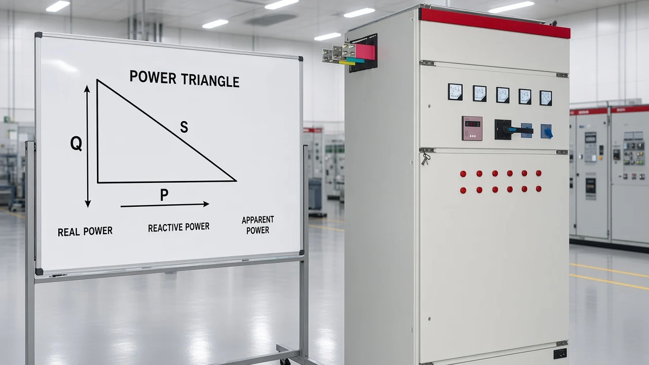
Apparent power is the hypotenuse of real and reactive power on the power triangle. For sinusoidal circuits you can draw a right triangle with these three quantities.
| Quantity | Symbol | Unit | Role |
|---|---|---|---|
| Real (active) power | P | W / kW | Does useful work |
| Reactive power | Q | VAR / kVAR | Energy exchanged with magnetic or electric fields |
| Apparent power | S | VA / kVA | Vector combination the supply must deliver |
Under those assumptions, S² = P² + Q², and power factor = P / S = cos φ (Electronics Tutorials — Power triangle; Engineering LibreTexts — Power triangle). Here φ is the phase angle between voltage and current.
Ideal inductors and capacitors absorb energy in one half-cycle and return it in the next, so their average real power is zero. They still force the source to carry reactive current. That is why a motor can draw more amperes than its kilowatt nameplate alone would suggest.
Reactive power is not “fake watts,” and it is not the main job of this article. For what Q represents inside an AC RL circuit, use a dedicated reactive-power guide. Here Q only exists so you can see why S can exceed P—and why PF falls when the reactive leg grows.
Lagging vs Leading Power Factor
A lagging power factor means current lags voltage; a leading power factor means current leads voltage. Industrial plants see lagging far more often because motors, transformers, and many magnetic loads are inductive.
| State | Voltage–current relationship | Typical cause | Plain reading |
|---|---|---|---|
| Unity | In phase | Purely resistive | PF = 1; all VA is real work |
| Lagging | Current behind voltage | Inductive loads (motors, transformers) | Common plant default |
| Leading | Current ahead of voltage | Capacitive loads / over-applied capacitors | Less common; can appear after correction |
Textbooks and open course notes use the same naming: positive/lagging for inductive, leading for capacitive (LibreTexts power factor section; All About Circuits — Calculating power factor). The ELI / ICE mnemonic (voltage leads current in an inductor; current leads voltage in a capacitor) is a memory aid, not a design rule.
For procurement language: if a meter or bill says “0.82 lagging,” read it as “eighty-two percent of apparent power is real work, and the current is trailing the voltage because the load looks inductive.”
Why Low Power Factor Matters on Plant Feeders
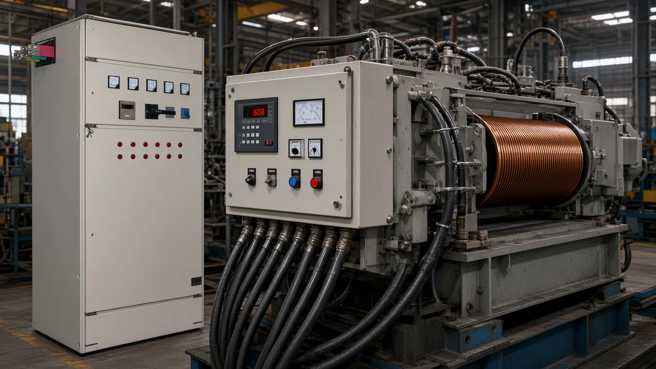
Low power factor means higher current for the same real work. Feeders, breakers, and transformers must carry the higher ampere demand even when process kilowatts stay flat. That extra current shows up as I²R heating, less spare capacity for new loads, and—depending on the tariff—utility surcharges or demand adjustments.
Independent textbooks put the inefficiency plainly: any power factor less than 1 means the wiring must carry more current than a purely resistive circuit would need for the same true power (All About Circuits). Plant-facing education repeats the same ratio language and notes that utilities may apply surcharges when power factor is low (Fluke power-factor overview — manufacturer education, not a References source).
From the field: On electrician forums, practitioners define power factor as the ratio of kW to kVA and note that installing capacitors is how buildings commonly improve that ratio—while also flagging possible penalties from the power company when the ratio stays low (Mike Holt Forum — Power factor). Thresholds and formulas are utility-specific; read your rate schedule instead of assuming a universal “fine.”
None of that requires inventing a payback spreadsheet. The definition-level takeaway is enough: poor PF is a current and capacity problem first, and a billing problem only where the tariff says so.

When cos φ Is Not the Whole Story
When voltage and current are sinusoidal, power factor equals the cosine of their phase angle. That is why older meters and textbooks say “PF = cos φ.”
Under distorted waveforms—common around VFDs, welders, and nonlinear electronics—a cos φ-only (displacement) reading can disagree with true power factor computed as real power divided by apparent power from simultaneous RMS quantities.
Measurement application notes state the limit directly: cos θ equals power factor only for sinusoidal voltage and current; a true power-factor meter computes the real-to-apparent ratio (Tektronix — Fundamentals of AC power measurements).
Wikipedia’s overview likewise notes that apparent power can exceed real power because of reactive energy exchange or waveform distortion (Wikipedia — Power factor).
For plant readers: treat cos φ as a clean-sine shortcut, not a universal identity. If the MCC is nonlinear, trust a meter that reports true PF (P/S), then decide whether correction, filtering, or both belong in the next project conversation.
Educational Examples: Reading 0.8, 0.5, and 0.95
These are labeled educational examples from stated inputs—not logged readings from a named plant.
| Example | Stated inputs | Result | How to read it |
|---|---|---|---|
| A — eighty percent | 80 kW and 100 kVA | PF = 0.80 (80%) | Four-fifths of apparent power is real work |
| B — half | 50 W and 100 VA | PF = 0.50 | Classic teaching ratio from AC measurement notes |
| C — common target language | Meter shows 0.95 | PF = 0.95 (95%) | Often discussed as a correction target; not a universal legal limit |
Example A answers the common PAA “what does 80% power factor mean?” directly: PF = 0.80. Example B matches the teaching case where useful power is half of apparent power. Example C answers “what does 0.95 power factor mean?” as a decimal target language—actual utility thresholds still come from the tariff, not from this table.
Is a power factor of 0.7 good on most industrial feeders? It is usually poor for capacity and often for billing.
At 0.7, only 70% of apparent power is real work, so current runs high for the kilowatts you need. Whether it triggers a charge depends on the utility.
When you need the arithmetic procedure—single-phase V·I paths, three-phase √3, simultaneous-reading discipline—open the sibling guide on how to calculate power factor. When you need the broader correction narrative, use power factor and power factor correction without treating this definition page as a buyer guide.
Where LV Static Compensation Fits After You Know PF
Once you understand that low lagging power factor means extra reactive demand—and higher current for the same kilowatts—the plant question becomes how to stage compensation. For distribution systems with relatively steady inductive loads, a low-voltage static reactive power compensation cabinet that switches capacitor groups from measured reactive demand or power factor is a direct next step.
The HYTBBJ Series Low-Voltage Static Reactive Power Compensation System is published for that job. It automatically switches capacitor groups according to measured reactive demand or power factor. It supports power-factor (reactive-current) control in manual and automatic modes, and monitors three-phase voltage, current, power factor, and compensation status.
The published model-code table includes a 0.4 kV system voltage level. The series hub frames static, dynamic, outdoor, and end-point options for staged control in industrial and commercial networks (Low Voltage Power Factor Compensation Series).
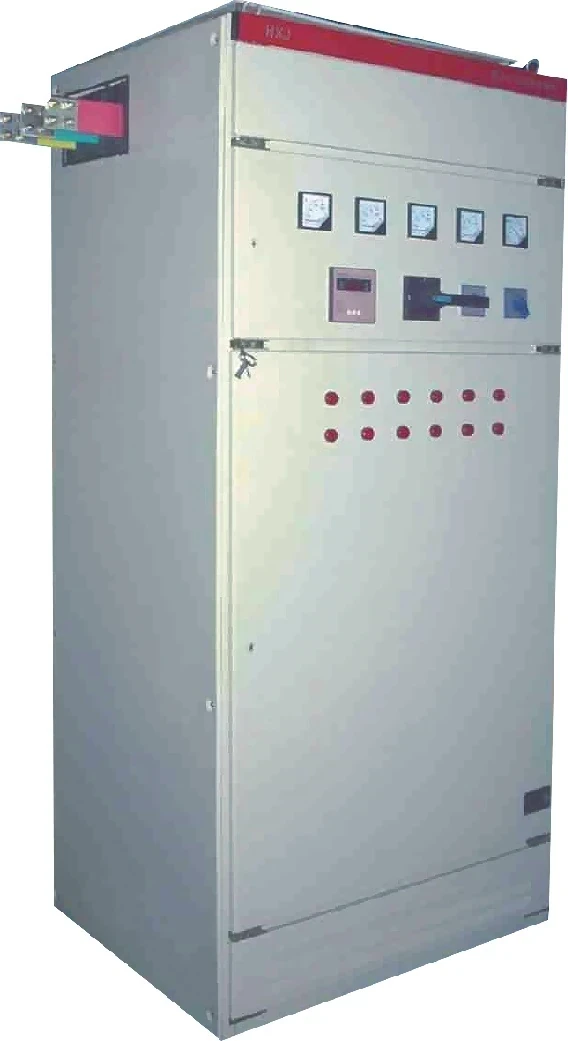
HYTBBJ is a better conversation when loads are relatively steady. Highly swinging plants may need a dynamic series instead. This page does not invent UL/NEC listings, SKUs, kilowatt-hour savings, or payback periods—only the printed product fit after the definition is clear.
Natural next step: bring a measured PF (and whether the load is steady or swinging) to the LV series page or an enquiry, and use the calculation sibling if you still need to derive PF from meter channels.
FAQ
What is meant by power factor in AC?
Power factor in AC is the ratio of real power to apparent power (P/S or kW/kVA). It states what fraction of the supplied volt-amperes is doing useful work at the metering point.
What does 80% power factor mean?
An 80% power factor means PF = 0.80. If apparent power is 100 kVA, real power is 80 kW in that educational framing—eighty percent of the VA is real work.
Is a power factor of 0.7 good?
Usually not for industrial feeders.
A reading near 0.7 leaves almost one-third of apparent power as reactive exchange, so line amperes stay high for the same process kilowatts.
Whether a utility surcharge applies depends on the rate schedule.
What does 0.95 power factor mean?
PF = 0.95 (95%) means ninety-five percent of apparent power is real. Many plants discuss 0.95 as a correction target; it is not a universal legal requirement without checking the tariff.
What is lagging vs leading power factor?
Lagging means current lags voltage (typical of inductive motors and transformers). Leading means current leads voltage (capacitive circuits, including over-applied capacitor banks).
Is power factor the same as cos φ?
Only when voltage and current are sinusoidal. Under distortion, true power factor is still real power divided by apparent power and may differ from a cos φ-only reading.
Why does low power factor increase current?
Because the supply must deliver the same real power plus a larger reactive component, apparent power and line current rise even when process kilowatts stay flat.
After I understand PF, how do I calculate it or correct it?
Use how to calculate power factor for the arithmetic procedure, and power factor and power factor correction for the correction narrative. For steady inductive LV loads, review the HYTBBJ static compensation system on the LV power factor series hub.
References
- Wikipedia — Power factor
- Electronics Tutorials — Power Triangle and Power Factor
- All About Circuits — Calculating Power Factor
- OpenStax University Physics Volume 2 — Power in an AC Circuit
- HyperPhysics — AC Power
- Tektronix — Fundamentals of AC Power Measurements
- Mike Holt Forum — Power factor
Humanizer self-audit (CHYN-DFT-PFAC-20261023-01): Pass 1 kept first-sentence H2 answers and labeled educational examples with no claim IDs in prose. Pass 2 cut filler and kept the forum callout without invented tariffs. Boundary: no UL/NEC, SKUs, kWh %, payback, or named-plant meter logs.