Zhejiang Hongyan Electric Co., Ltd.















04Oct,2026
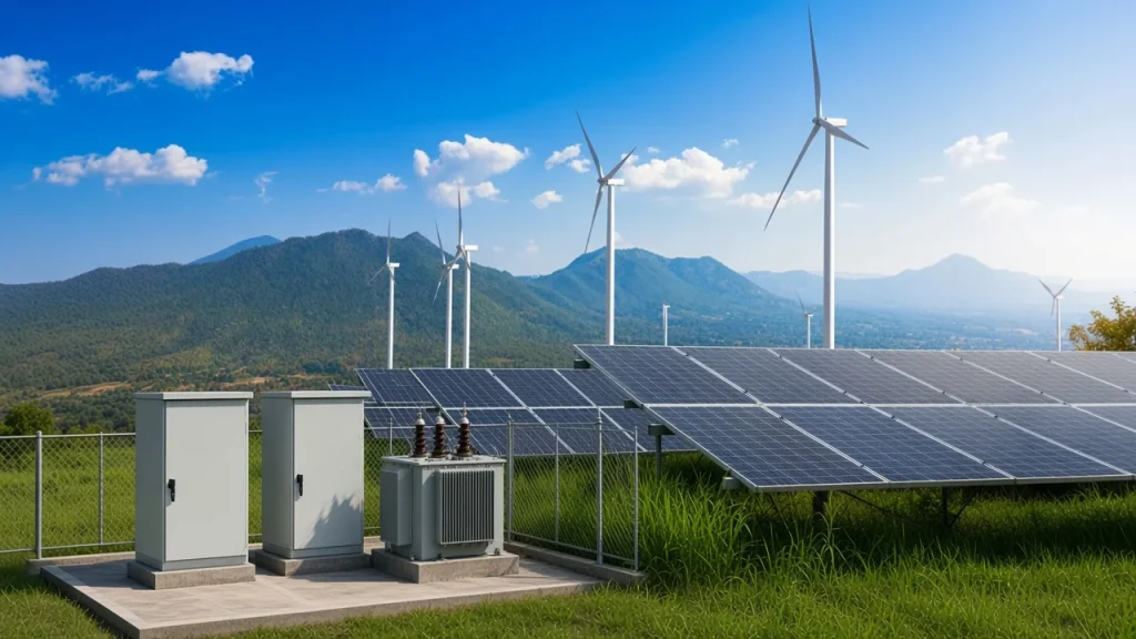
Power Conditioning Equipment for Grid-Connected Plants at the PCC
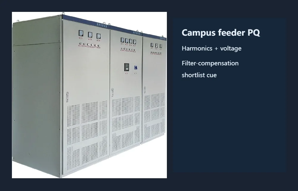
Shortlist AHF, SVG and DVR at the PCC for grid-tied inverter plants: harmonics, flicker, vars and sag hardware, not a UPS or home rack conditioner.
Read insight  HYSVGC Series Hybrid Static Var Dynamic Compensation Device
 HYSVG Static Var Generator (SVG)
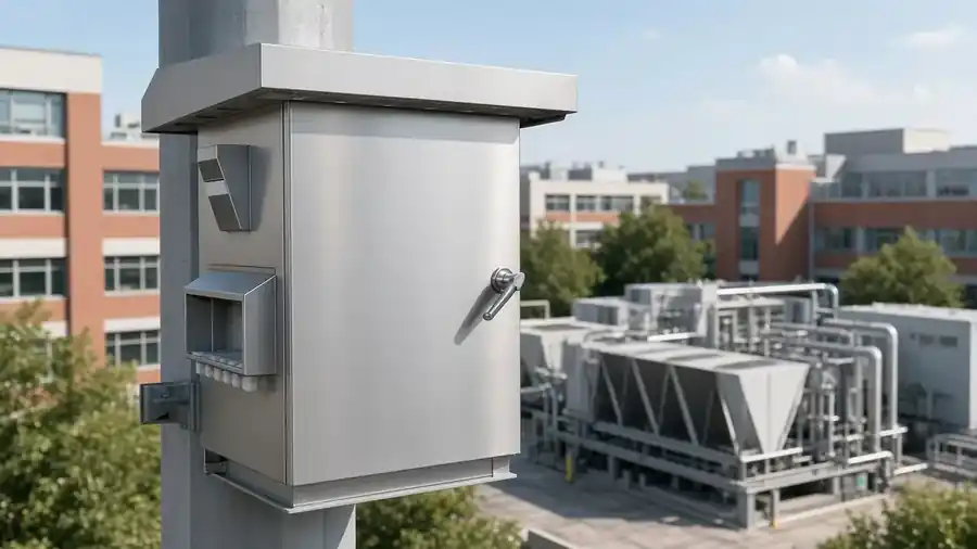
 HYSVG Pole-Mounted Outdoor Three-Phase Imbalance Correction Device
 HY-HPD Series Harmonic Protection Device
 HYSVG Series High Voltage Dynamic Reactive Power Compensation Device
 HYAPF Series Active Power Filter
 HYTSF Series Low-Voltage Dynamic Filtering & Compensation Device
 HYMSVC Series High-Voltage Dynamic Filtering and Compensation Device
 HYLX Zero-Sequence Current Absorber
 HYFCKRL Series Ferroalloy Submerged Arc Furnace Harmonic Filtering & Reactive Compensation System
 HYFC Series Low-Voltage Static Passive Harmonic Filter & Compensation Device
 HYFC-ZP Series Passive Harmonic Filter & Energy-Saving Compensation Device for Intermediate-Frequency Furnaces
 HYFC-ZJ Series Passive Harmonic Filter & Reactive Compensation Device for Rolling Mills
 HYFC-BP Series Passive Harmonic Filter for VFD Systems
 HYTSC High-Voltage Dynamic Reactive Power Compensation System
 HYTBBT Series On-load Voltage & Reactive Power Regulation System
 HYTBB Series Medium & High Voltage Reactive Power Compensation System – Outdoor Box Type
 HYTBB Series Medium & High Voltage Reactive Power Compensation System – Indoor Frame Type
 HYTBB Medium and High Voltage Reactive Power Compensation Cabinet
 HYTBBW Series Pole-Mounted High Voltage Reactive Power Compensation Device
 HYSVC Series High Voltage Dynamic Reactive Power Compensation and Filtering Device
 HYTBB Series High-Voltage Reactive Power Compensation Device – Outdoor Frame Type