
 Zhejiang Hongyan Electric Co., Ltd.






































The 3 types of power factor you meet on plant meters and textbooks are lagging, leading, and unity. Classify which type applies on your bus before you size capacitors or set an automatic controller—because the correction direction for lagging inductive loads is not the same move you make when the bus is already leading.
This guide locks that three-type taxonomy, shows how each type shows up in real distribution, and then points to low-voltage static compensation only after the classification is clear. For the basic P/S definition and calculation steps, use the live what is power factor in an AC circuit and how to calculate power factor pages after you finish here.

What the 3 Types of Power Factor Are
Power factor (PF) is the ratio of real / active power to apparent power—P/S. For a clean sinusoidal circuit it is also cos φ, where φ is the angle between voltage and current (Wikipedia — Power factor; OERTX AC Circuit Analysis).
The three types named across educational pages for this keyword are not three different formulas. They are three operating senses of that ratio:
- Lagging power factor — current lags voltage (inductive).
- Leading power factor — current leads voltage (capacitive).
- Unity power factor — voltage and current are in phase (PF = 1).
| Type | Phase relationship | Typical load signature | What correction usually means |
|---|---|---|---|
| Lagging | Current behind voltage | Motors, transformers, many inductive plants | Add capacitive vars (capacitor banks / APFC) |
| Leading | Current ahead of voltage | Capacitor banks, over-correction, some sync machines | Reduce capacitive vars; do not keep adding caps |
| Unity | In phase; PF = 1 | Pure resistive, or inductive and capacitive cancelled | Hold the target; avoid hunting past unity |
Do not confuse these three PF types with the three power quantities—real (P), reactive (Q), and apparent (S)—which form the power triangle (Electronics Tutorials — Power triangle). Those quantities explain the math. Lagging / leading / unity name how the phase relationship behaves on the bus.
Lagging Power Factor
A lagging power factor means the load current lags the supply voltage. That is the normal signature of inductive equipment: induction motors, transformers, and many lighting ballasts pull magnetizing vars, so the current waveform peaks after the voltage waveform (OERTX; Schneider Electric FAQ FA212521).
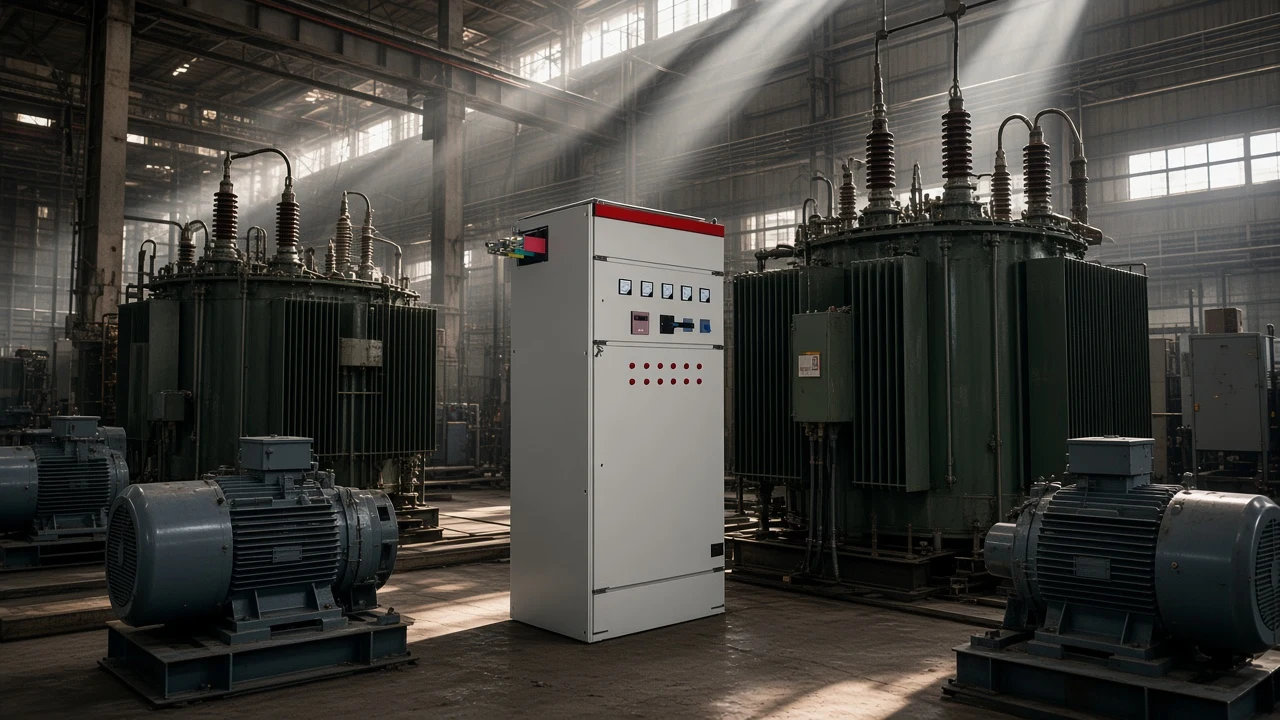
On a plant floor that usually looks ordinary. An MCC feeding conveyors and pumps, a transformer lightly loaded at the start of a shift, or a welding bay with inductive arcs will push the meter toward lagging long before anyone installs a capacitor cabinet.
Industrial teaching material treats that pattern as the default. Motors and transformers typically present a lagging power factor until something supplies leading vars in return (OERTX).
Why plants care: the same kilowatts still require more amperes when PF is low, so feeders, transformers, and generators carry extra current that does no net work. Utility contracts may also watch monthly power factor—but thresholds and formulas vary by tariff, so treat “improve lagging PF” as an engineering conversation with the rate schedule open.
Leading Power Factor
A leading power factor means the load current leads the supply voltage. Capacitive load / capacitor bank circuits do that: power-factor correction capacitors, cable capacitance on lightly loaded feeders, and some synchronous machines when they furnish vars (Schneider FA212521; Wira Electrical — types of power factor).
In correction projects the important story is miss-application. Capacitors are the standard fix for lagging inductive demand.
If stages stay online after motors stop—or if the bank is oversized for the residual inductive load—the net reactive power flips and the bus goes leading. Technical notes warn that miss-applied capacitor correction is a common path into leading PF, and that leading conditions can stress standby generators and voltage control (ABB Technical Note 174 — Introduction to Power Factor).
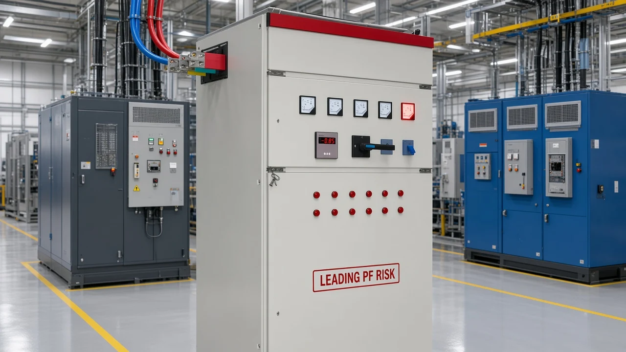
From the field: When a night shift leaves every capacitor stage forced online against a quiet base load, the meter can swing from lagging into leading. That is not “better than unity”—it is a different type, and the next move is usually to drop stages or raise the controller deadband, not to add another bank.
Unity Power Factor
Unity power factor means PF = 1: real power equals apparent power at the metering point, and for the ideal sinusoidal case the phase angle is zero (Wikipedia — Power factor; OERTX). Voltage and current line up. Net reactive power on the power triangle collapses toward zero.
A purely resistive process—resistance heating, some simple resistive lines—can sit at or near unity without capacitors. Corrected plants can also approach unity when inductive and capacitive vars cancel.
That does not mean every feeder should chase 1.000 as a brittle setpoint. Stepped banks, swinging motors, and harmonic current all make exact continuous unity harder than the textbook picture.
The sibling article Is a Power Factor of 1 Possible? owns that deeper practicality discussion. Here, unity is simply the third type: in-phase operation, not a sales promise.
How to Classify PF Type Before You Correct
Classification comes before shopping. Read the meter language, the load mix, and the recent switching history—not only the decimal number.
- Look at the type word or icon, not only 0.xx. Many displays show “lag,” “lead,” or a signed convention. Lead/lag language tracks whether current is behind or ahead of voltage. The plus/minus sign in front of the number may follow IEEE or IEC conventions that do not equal “leading = negative” by themselves (Schneider FA212521). If two instruments disagree on the sign, open the manuals before you argue about the plant.
- Map the load signature. Motor-heavy and transformer-heavy buses usually start lagging. Capacitor-heavy or over-corrected buses lean leading. Resistive process lines lean toward unity.
- Check what changed recently. New banks online, a process line offline, or a forced-manual capacitor mode often explains a sudden flip from lagging to leading.
- Choose direction only after the type is clear. Lagging inductive demand usually calls for capacitive vars. Leading demand usually calls for fewer capacitive vars. Unity (or a stable near-unity target) calls for holding and fine-tuning—not another round of “add more capacitors.”
Community metering threads make the same literacy point in plain language: V×I is apparent power (VA), a wattmeter-style reading is needed for real power, and only then is power factor trustworthy (EEVblog — electronics math and power factor).
| If you see… | Likely type | First move before buying correction |
|---|---|---|
| Motors / transformers, no caps or under-corrected | Lagging | Estimate inductive kvar; plan staged capacitive correction |
| Caps online with light inductive load | Leading | Reduce stages / revisit setpoint; do not add more caps |
| Resistive process or well-balanced correction | Unity / near unity | Confirm target vs tariff; avoid hunting past unity |
| Confusing +/− on two meters | Unknown until manuals checked | Align IEEE/IEC convention, then re-read lead/lag |
For a hands-on meter and waveform check once you already know you need lead/lag diagnosis, use How to Know if Power Factor Is Leading or Lagging. This page stops at classification for type selection.

Displacement vs True Power Factor (Not a Fourth “Type”)
Some datasheets and meters also print displacement power factor (fundamental voltage–current angle only) and true power factor (real power over apparent power including harmonic content). Those labels answer a measurement question under distorted waveforms. They are not a second set of “three types” that replaces lagging / leading / unity (ABB Technical Note 174).
A bus can still be lagging or leading at the fundamental while harmonics pull true PF lower than the displacement reading. If nonlinear loads dominate, classify the phase type and also ask what the meter means by “PF” before you celebrate a near-unity number.
Keep the taxonomy straight: lagging / leading / unity name the operating sense. Displacement / true name how much harmonic burden is inside the reading.
Which LV Static Compensation Fits After You Classify
After you confirm lagging power factor from relatively steady inductive loads, a low-voltage static compensation cabinet that switches capacitor groups from measured reactive demand or power factor is a logical next step.
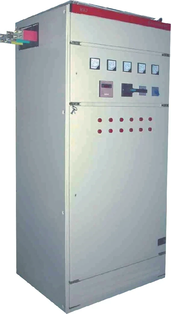
CHYN’s HYTBBJ Series Low-Voltage Static Reactive Power Compensation System is built for that job. It automatically switches capacitor groups according to measured reactive demand or power factor, supports manual and automatic PF/reactive-current control, and monitors three-phase voltage, current, and power factor.
The published model-code table includes a 0.4 kV system voltage level. Switching delay is adjustable 0–120 s with a special fast mode ≤1 s on the product page.
When it is not the first fit: if the bus is already leading, adding another static capacitor stage usually worsens the type problem.
If load swings are large and fast, review the dynamic option on the same Low Voltage Power Factor Compensation Series hub (HYTBBD) rather than forcing a static bank to chase every peak. End-point motors that need local compensation may point toward HYTBBM. Bring your measured type, voltage, and load steadiness notes when you compare options on the LV Power Factor Compensation Series hub.
For how correction sits on a plant bus after you know the type, see How Power Factor and Power Factor Correction Work on Plant Buses.
FAQ
What are the 3 types of power factor?
Lagging, leading, and unity.
Lagging means current lags voltage (inductive). Leading means current leads voltage (capacitive). Unity means PF = 1 with voltage and current in phase.
What causes lagging power factor?
Inductive loads—especially motors and transformers—draw current that lags voltage, so the plant meter reads a lagging power factor until capacitive vars offset that demand.
What causes leading power factor?
Net capacitive behavior: correction capacitors, cable capacitance on light load, or machines furnishing vars. Over-corrected capacitor banks are a common plant cause.
Is unity power factor the same as PF = 1?
Yes. Unity is the name for PF = 1, where real power equals apparent power for that measurement and the ideal sinusoidal phase angle is zero.
Are real, reactive, and apparent power the three types of power factor?
No. Real, reactive, and apparent power are the three power quantities on the power triangle. The three PF types are lagging, leading, and unity.
How do IEEE/IEC meter signs relate to leading vs lagging?
Lead/lag describes whether current is ahead of or behind voltage. The plus/minus sign on a display follows IEEE or IEC conventions and is not automatically the same as the lead/lag word—check the instrument manual (Schneider FA212521).
Should I add capacitors if PF is already leading?
Usually no. Extra capacitance pushes the bus further leading. Reduce stages or revisit the controller setpoint first.
Where does displacement vs true PF fit?
They describe whether the meter uses the fundamental angle only (displacement) or includes harmonic content in P/S (true). They do not replace the lagging / leading / unity types.
References
- Wikipedia — Power factor — Definition of PF, unity, lagging/leading naming.
- OERTX — Chapter 14 AC Circuit Analysis (Power Factor) — PF = cos φ; lagging inductive / leading capacitive teaching.
- Electronics Tutorials — Power triangle — Power quantities on the triangle vs PF types.
- Wira Electrical — What is Power Factor and Why is it Important — Independent education listing unity / lagging / leading types.
- Testbook — Power Factor types — Explicit three-type taxonomy: leading, lagging, unity.
- EEVblog Forum — Electronics math and power factor — Community language separating VA, watts, and PF.