
 Zhejiang Hongyan Electric Co., Ltd.






































How to know if power factor is leading or lagging starts with the current-versus-voltage relationship: lagging means current lags voltage (typical inductive loads); leading means current leads voltage (typical capacitive loads). Sections below add a VAR-flow check, explain why a bare ± on a power quality meter / recorder is convention-dependent, and show which correction direction—and which LV compensation path—fits after the diagnosis.
If you only remember one rule, remember that lead/lag names the current relative to voltage. That is also how to know if power factor is lagging or leading when the secondary wording appears on a work order. Power factor (leading / lagging) is the diagnosis job; the magnitude alone is only half the story.

Leading vs Lagging: Current Relative to Voltage
A lagging power factor means current lags voltage, which is typical of inductive loads. A leading power factor means current leads voltage, which is typical of capacitive loads.
In plant English, induction motors, transformers, and many magnetics pull magnetizing current that trails the voltage waveform. A capacitive load / capacitor bank pushes current that arrives ahead of the voltage.
Power factor itself remains the ratio of real power to apparent power. Leading versus lagging only names which side of unity you sit on for reactive behavior. For the arithmetic of PF = kW ÷ kVA, see how to calculate power factor.
University circuit texts state the same phase story with a signed teaching convention: positive PF described as lagging and inductive, and capacitive cases marked as leading (LibreTexts power triangle chapter). Encyclopedia summaries keep the same lead/lag vocabulary for current relative to voltage (Wikipedia article on power factor).
Waveform and Phasor Checks You Can Trust
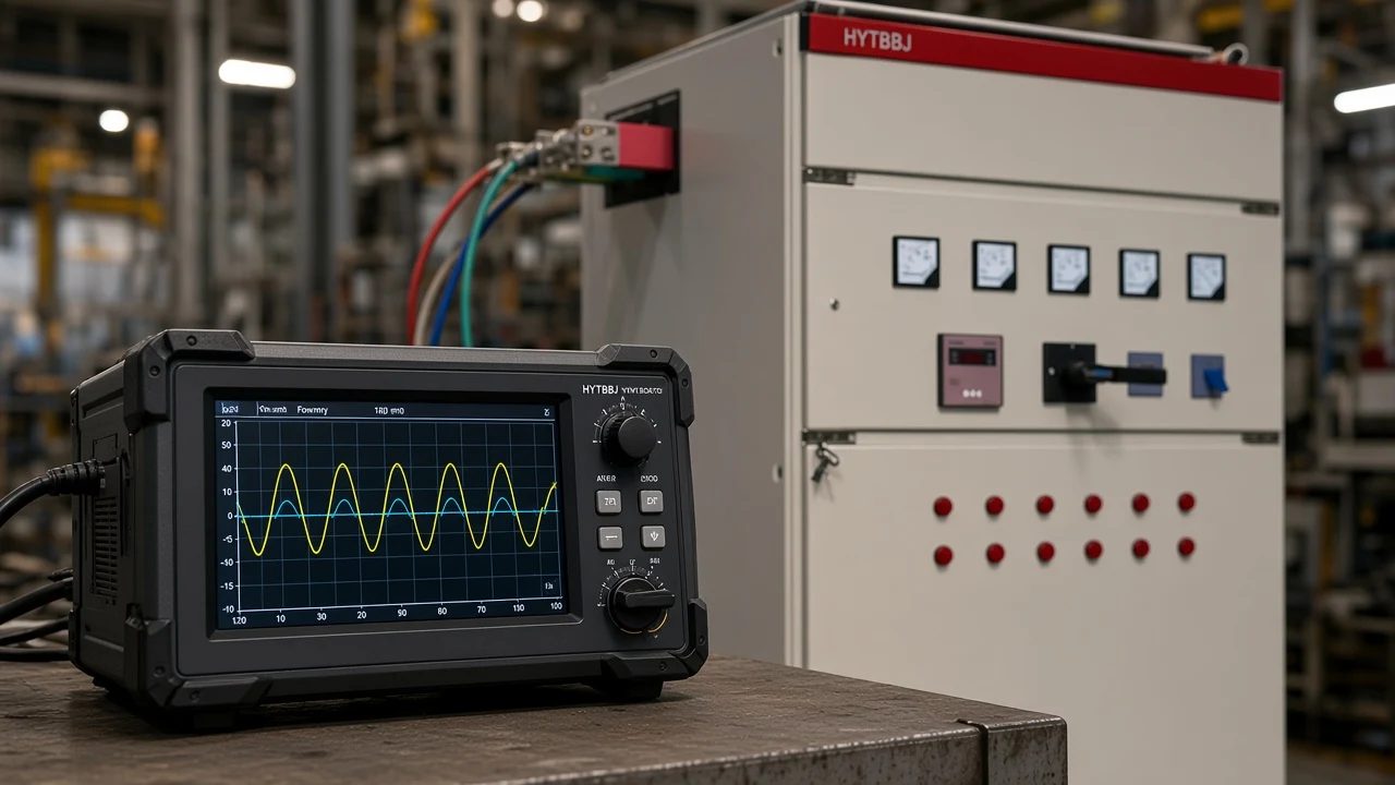
On a scope or analyzer, see whether current zero-crosses before or after voltage—and verify current-probe direction. That is the field version of the phase angle / waveform check.
Practical steps:
- Capture voltage and current on the same interval at the point of interest.
- Compare peaks or zero crossings: current after voltage → lagging; current before voltage → leading.
- Confirm CT or clamp orientation. A reversed clamp flips lead and lag on the display even when the load did not change.
Motor feeders are usually inductive, so current should lag voltage when the setup is correct. If a motor circuit suddenly looks strongly leading, treat probe direction as a first suspicion before blaming the process.
Educational textbook walkthroughs use the same idea with numbers. For a 100 VA apparent load at a −30° phase angle, PF = cos(−30°) ≈ 0.866 leading and real power is about 86.6 W (LibreTexts power triangle chapter). Treat that as labeled teaching arithmetic, separate from any logged board reading.
VAR Flow: Absorbing vs Supplying Reactive Power
From the load’s side, lagging means absorbing VARs; leading means supplying VARs. Reactive power (VAR / kvar) is the second independent check when phase labels feel slippery.
Loads that receive VARs—classic induction motors and transformers—are described as lagging. Loads that furnish VARs—capacitor banks and some synchronous machines—are described as leading (Power Factbook power factor basics).
Generator naming can reverse relative to load language. State whether you are speaking from the load terminals or from a generation source before you argue about the word “lagging.”
Capacitor banks and some over-excited synchronous machines contribute leading behavior. For excitation and sync-motor detail, keep the cross-links light: over-excited synchronous motor reactive power and phasor diagram at leading power factor—the diagnosis here stays on plant meters, not a motor textbook.
Meter Signs: IEEE, IEC, and Vendor Conventions
Read any plus or minus on the PF display only after you know that instrument’s IEEE / IEC PF sign convention—or the vendor rule printed in its manual.
Important: Leading and lagging describe whether current leads or lags voltage. The ± printed beside a power-factor reading follows the standard or vendor rulebook for that instrument—plants cannot borrow one meter’s sign map for every other meter on site.
Under the IEC convention described in a Schneider Electric FAQ on kW, kvar, and PF signs, PF sign follows real-power direction, independent of inductive versus capacitive load type. Under the IEEE convention on that same FAQ, inductive loads show negative PF and capacitive loads show positive PF.
Vendors still disagree with each other. Some power recorders mark negative PF as lagging and positive as leading (PMI sign-convention white paper). Other meters encode a slight lag near +1 and a slight lead near −1 (Elkor knowledge base article on PF sign).
So lagging power factor positive or negative depends on which rulebook the display follows. Open the instrument manual for that power quality meter / recorder, then decide.

| Convention / source | What ± usually tracks (as documented) | Practical plant habit |
|---|---|---|
| Lead/lag words | Current relative to voltage | Prefer labeled “lead” / “lag” or VAR direction |
| IEC (Schneider FAQ) | Real-power flow direction | −PF may still be inductive under IEC |
| IEEE (Schneider FAQ) | Inductive → negative PF; capacitive → positive PF | Match this only if the meter claims IEEE |
| Example vendor A (PMI) | −PF lagging; +PF leading | Confirm in that manual |
| Example vendor B (Elkor) | Lag near +1; lead near −1 | Opposite vendors exist—compare manuals |
Leading vs Lagging Power Factor at a Glance
Leading vs lagging power factor is easiest to scan as a side-by-side decision table. Use it after the phase and VAR checks, then confirm with the meter rulebook.
| Check | Lagging | Leading |
|---|---|---|
| Current vs voltage | Current lags voltage | Current leads voltage |
| Typical load | Inductive (motors, transformers) | Capacitive (banks, some sync machines) |
| VAR from load view | Absorbing / requiring VARs | Supplying / furnishing VARs |
| Usual correction direction | Add capacitive compensation | Reduce capacitance or add inductive reactance |
| Bare 0.95 on a display | Needs lead/lag or VAR context | Needs lead/lag or VAR context |
A bare 0.98 without a lead/lag label or a known sign convention does not tell you which side you are on. Ask the meter for VAR sign, a lead/lag flag, or a documented convention before you stage another capacitor step.
Plant Scenarios: Motors Lagging, Banks Over-Correcting
Motor-heavy MCCs usually read lagging; light-load nights with banks left on can tip leading. Walk both scenes before you change hardware.
Scenario A — lagging motors. A manufacturing feeder full of induction motors absorbs VARs. Waveforms show current behind voltage. Capacitive power factor correction is the usual direction once you confirm the reading is free of a reversed-CT story.
Scenario B — over-corrected leading. The same plant leaves fixed banks online after the night shift drops load. Net current leads voltage, or the load appears to supply VARs to the utility. Adding more capacitors deepens the leading condition.
PE-exam and field threads stress the same angle discipline: lead/lag on power factor refers to current relative to voltage, lagging loads consume reactive power under the passive convention, and leading loads supply it. Practical metering threads also remind readers that Vrms × Irms is apparent power, while a wattmeter-style average of v·i is needed for real power before PF is trusted (EEVblog thread on electronics math and power factor).
After You Know: Capacitors, Reactors, or Less Capacitance
Lagging inductive loads are commonly corrected with capacitive compensation. A net leading condition is corrected by reducing capacitance or adding inductive reactance—extra capacitors push the wrong way.
That is the power factor correction fork:
- Confirmed lagging / absorbing VARs → stage capacitors or an automatic capacitor bank toward the target PF.
- Confirmed leading / supplying VARs → open steps, detune fixed banks, or add reactor capacity as the design requires.
- When reactive demand swings, staged or dynamic switching replaces a single fixed bank (LibreTexts power triangle chapter).
Practical correction texts also note that industrial motor loads are usually lagging, so parallel capacitors are the common first correction tool once true and apparent power are known (LibreTexts practical power factor correction).
Which HYTBBJ Fit After a Lead/Lag Diagnosis
HYTBBJ automatically switches capacitor groups from measured reactive demand or power factor for relatively steady inductive loads. Choose it after you have confirmed a lagging inductive story that needs staged capacitance—skip it while the feeder still measures net leading.
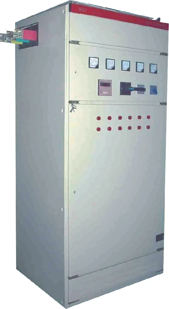
The HYTBBJ Series Low-Voltage Static Reactive Power Compensation System is aimed at manufacturing, buildings, and public facilities with relatively steady inductive demand. It monitors three-phase voltage, current, and power factor. The published model code table includes a 0.4 kV system voltage level.
When inductive demand swings hard, look at the HYTBBD Series Low-Voltage Dynamic Reactive Power Compensation System. HYTBBD targets distribution with strong inductive-load fluctuation and lists a target power factor of 0.95 or higher.
Browse the Low Voltage Power Factor Compensation Series for static, dynamic, outdoor, and end-point options after the lead/lag diagnosis is locked.
FAQ
How do I know if power factor is leading or lagging?
Check whether current leads or lags voltage, confirm whether the load is absorbing or supplying VARs, then interpret any ± only after you know the meter’s IEEE, IEC, or vendor rule.
What is the difference between leading and lagging power factor?
Lagging means current lags voltage and the load typically absorbs VARs. Leading means current leads voltage and the load typically supplies VARs.
Is a capacitor lagging or leading?
Capacitor banks are capacitive contributors: they produce leading current relative to voltage and are associated with leading power factor on the load side.
What does it mean if the power factor is leading?
It means current leads voltage and the measured point is behaving capacitively—often from banks, cables, or over-excited machines. Correction usually means less capacitance or added inductive reactance, rather than more capacitors.
Why does my meter show a negative power factor?
Because that instrument’s sign convention says so. IEC-style rules, IEEE-style rules, and vendor manuals disagree; read the manual before equating “−” with leading or lagging.
Does 0.95 alone tell me leading or lagging?
No. Magnitude without a lead/lag label, VAR sign, or documented convention does not encode the side.
Lagging vs leading — which needs capacitors?
Lagging inductive conditions are the usual capacitor case. Leading net conditions need reduced capacitance or inductive reactance.
Can generator language reverse leading and lagging?
Yes. Generator naming for leading and lagging can reverse relative to load language—state the viewpoint before you argue the label.