
 Zhejiang Hongyan Electric Co., Ltd.






































Over excited synchronous motor reactive power leading or lagging is settled by field current. Raise excitation past the unity-power-factor point and the motor draws leading current and supplies reactive power. Drop it below that point and the same machine absorbs vars at a lagging power factor.
The rest of this page unsticks the generator wording that flips “leading” and “lagging,” shows how the V-curve steers the sign, runs a labeled educational plant balance, and marks when a capacitor bank or high-voltage SVG still has work after the motor is already at field limit.
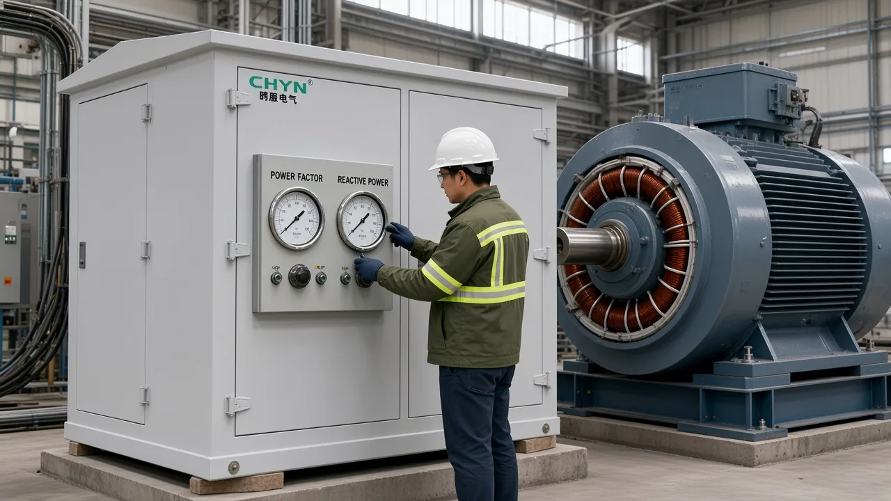
Over-Excited Means Leading Current and Vars Out
An over-excited synchronous motor draws leading current and supplies reactive power. That is the plant meaning of over excited synchronous motor leading power factor supplies reactive power.
Over-excited means the internal voltage is higher than the value that matches terminal voltage at that load. University notes write the test as Ef > VT; phasor teaching writes Ea cos δ > Vt (SIU Lesson 18 on synchronous motor operation; Electrical Academia synchronous-motor phasor page).
From the bus the machine looks like a capacitive load. Leading current offsets lagging vars from nearby induction motor and transformer magnetizing current.
Nameplates often read unity or 0.8 power factor. A 0.8 rating is built to carry extra field and armature current so the motor can stay on the leading side while it still delivers shaft load.
Under-Excited Means Lagging Current and Vars In
An under-excited synchronous motor absorbs vars at a lagging power factor. That is the underexcited synchronous motor reactive power leading or lagging answer: lagging, and absorbing.
Field current below the unity-power-factor point leaves internal voltage short of the matching value. The armature then takes magnetizing current from the bus, so the motor behaves like an inductor (Wikipedia synchronous condenser article).
The unity-power-factor excitation is the V-curve minimum, where the motor exchanges almost no reactive power. Armature current is smallest there because only the real-power component remains.
| Excitation | Power factor | Reactive power | Looks like |
|---|---|---|---|
| Over-excited | Leading | Supplies vars | Capacitor |
| Unity | In phase | Near-zero exchange | Real power only |
| Under-excited | Lagging | Absorbs vars | Inductor |
A mill motor that idles with the field wound down will start importing vars even though the shaft is barely loaded. That is the under-excited side of the same machine, not a different motor type.
Why Generators Use the Opposite Leading and Lagging Words
The over-excited machine still supplies vars; a generator just labels that lagging. An overexcited generator delivers Q at a lagging power factor because engineers read current from the source toward a lagging load.
Vars flow from the over-excited machine toward under-excited buses or machines. METU lecture notes put the same rule in one line: reactive power flows from the over-excited side to the under-excited side (METU EE-362 P and Q flow notes).
PE-exam threads mix the two vocabularies. One poster mapped both an over-excited generator and an over-excited motor to “leading PF”; replies corrected the generator to lagging while keeping the motor leading, and then stated the shared fact: whenever the machine is over-excited it delivers Q (Engineerboards thread on PF versus sync motor and generator excitation).
If a relay printout says “vars out,” treat that as leading for a motor and lagging for a generator. The Q arrow did not change; only the viewpoint did.
How the V-Curve Shows Leading or Lagging
Field current past the minimum-ampere point is the leading side. Plot armature current against field current at constant shaft load and the curve looks like a V.
On the V-curve, more field current than the minimum-ampere point is the leading side. Less field current is lagging. The inverted-V plot of power factor versus field current peaks at unity (TutorialsPoint page on V-curves and inverted V-curves).
Over-exciting does not make the motor faster or add shaft kilowatts; it steers reactive power. Speed stays locked to line frequency.
Approximate cylindrical-rotor teaching writes Q = 3 Vt (Ef cos δ − Vt) / Xs when armature resistance is neglected. Raise Ef and Q moves from absorbed to supplied.
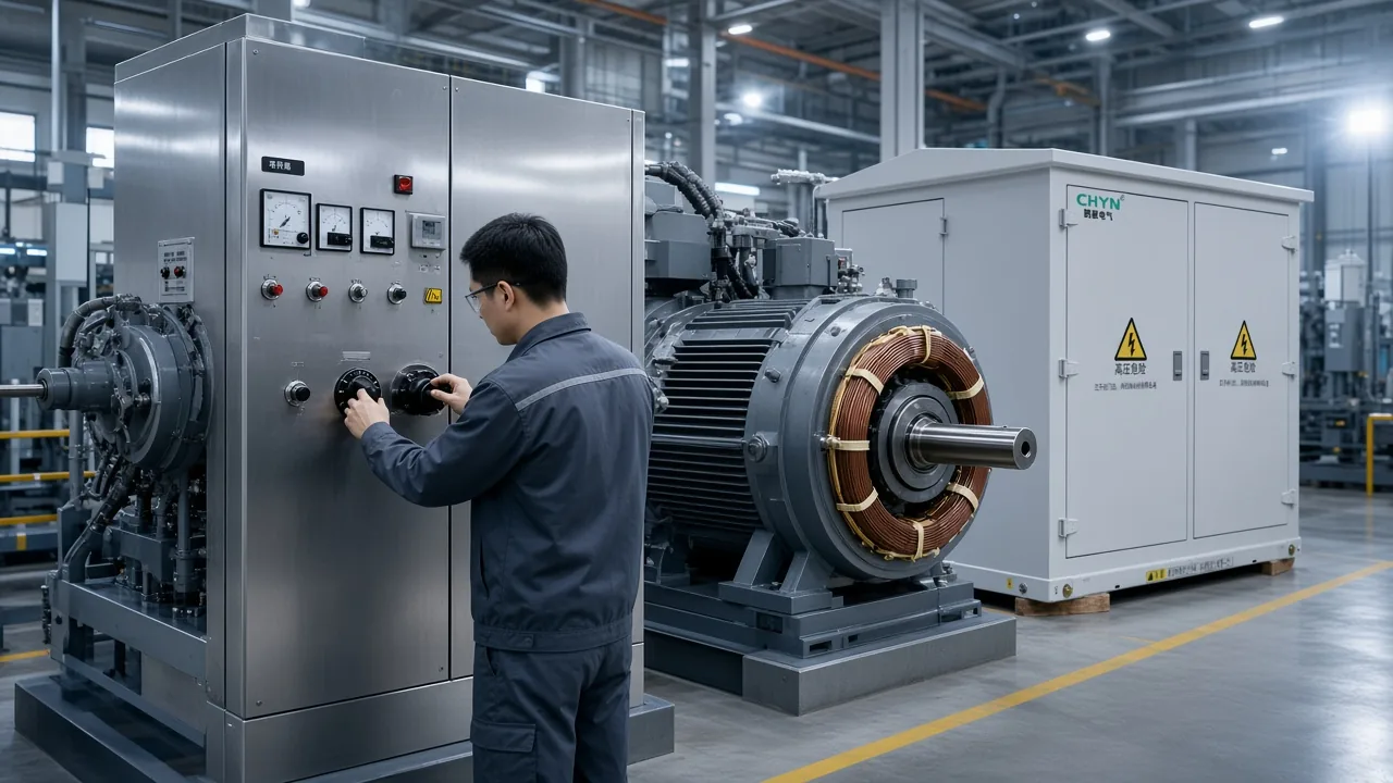
Remove shaft load from a motor that was sitting at unity and the operating point slides toward leading. That is why an unloaded over-excited machine becomes a synchronous condenser.
Worked Example: Balancing Plant Vars With One Motor
A textbook plant balance shows the leftover kvar the motor must supply. The numbers below are worked arithmetic from stated inputs, not meter logs from a named site.
Independent machine notes use this plant: 1,500 kW at 0.80 lagging, which is 1,125 kvar, plus a new synchronous motor drawing 300 kW, with a target of 0.95 lagging on the combined bus (Electronics Guide page on synchronous machines).
| Stated input | Value |
|---|---|
| Existing plant real power | 1,500 kW |
| Existing plant power factor | 0.80 lagging |
| Existing plant reactive | 1,125 kvar |
| Added motor real power | 300 kW |
| Combined real power | 1,800 kW |
| Target plant power factor | 0.95 lagging |
The combined bus at 0.95 lagging can draw at most 591.6 kvar. The motor must then supply 533.4 kvar.
In that textbook example, the motor must supply about 533 kvar at a leading 0.49 power factor. Apparent power on the motor is 612 kVA.
That is why a 0.8-PF nameplate exists. The machine has to be built for both shaft kilowatts and the leading vars you asked it to export.
If the remaining induction motor load later falls, the same field setting over-corrects. Recheck the V-curve point instead of leaving yesterday’s excitation locked.
When the Synchronous Motor Is Not Enough
Field, heating, remaining loads, and leading-PF risk still leave a gap. With little or no shaft load, the same over-excited machine is a synchronous condenser.
Some plants run a continuously loaded synchronous motor leading on purpose; pushing past a strongly leading target can still be charged or risky. Electrician forums describe compressor synch motors that stay online whenever the plant needs air, and occasional unloaded condensers; one long reply treats more than 0.95 leading as a risk band to avoid (Mike Holt Forum thread on leading and lagging power factor).
From the field: A Mike Holt starter thread asked whether over-exciting could “produce a power factor over 1.0.” The correction was blunt: it is a leading power factor, not a number greater than 1.0, and some steel mills once ran an unloaded machine just for vars before capacitors became the cheaper everyday tool (Mike Holt Forum thread on starting a synchronous motor).
Leading power factor is still a number between 0 and 1; the sign is lead, not PF>1. Treat “greater than unity” as a wording error, not an operating target.
A fixed bank delivers fewer vars as the bus sags; a machine or converter can still push vars into a weak bus. Capacitor reactive output scales with voltage squared, which is why a sagging feeder starves a shunt bank just when support is wanted (Wikipedia synchronous condenser article).
The motor also has a thermal and stability ceiling. Extra field current raises copper and core loss; too little field is the more dangerous underexcited side because pull-out torque falls.
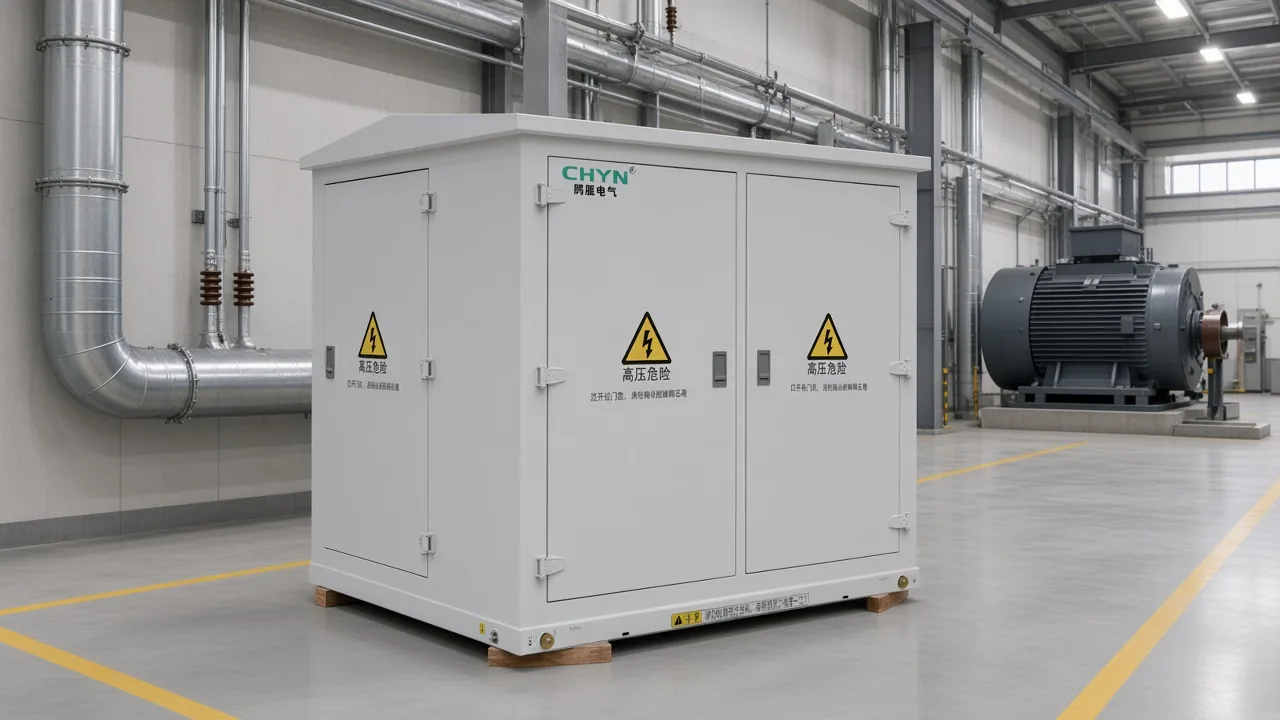
When HYSVG Is the Fit on the Same High-Voltage Bus
Continuous inductive-to-capacitive vars cover leftover or swinging HV duty. Use the motor for the stable share it can hold; give the remainder to hardware that can reverse Q.
The HYSVG Series High Voltage Dynamic Reactive Power Compensation Device supplies or absorbs vars continuously on 6 to 35 kV buses when a switched bank cannot track the duty. It is aimed at metallurgy, mining, renewable-energy connections, and large industrial substations where load change or voltage swing outruns a capacitor step.
The published table lists 6–35 kV, ±1 to ±100 Mvar, and a response time under 5 ms. Printed overload is 1.2 × rated value for 1 min, and efficiency is at least 99.2% under rated conditions.
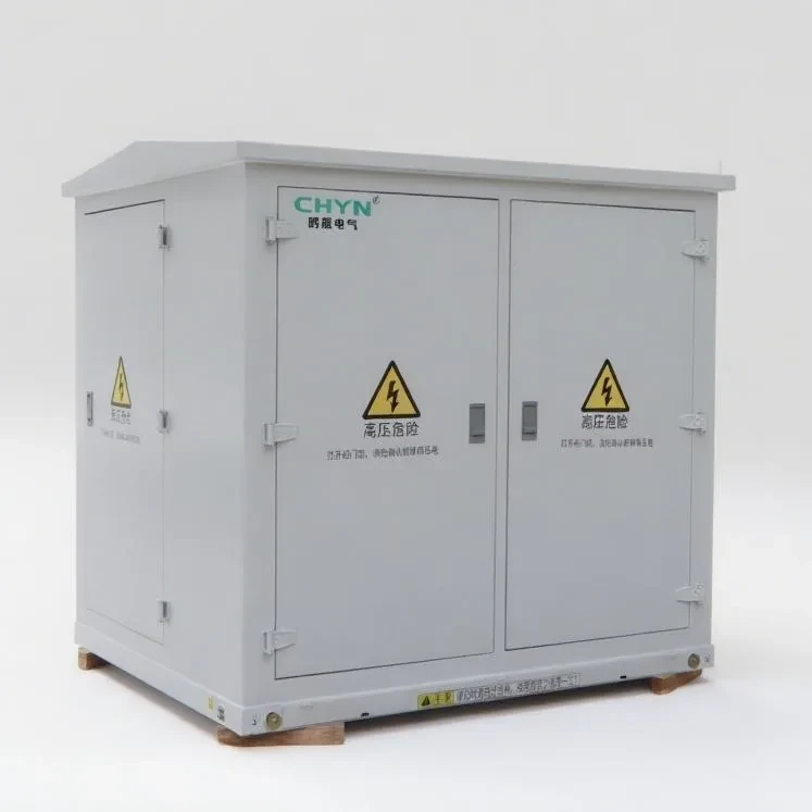
Browse the High Voltage Power Factor Compensation Series when the leftover vars are still capacitive steps on a steady bus. How many capacitor kvar to switch is a separate calculation after you know the leftover vars; use how to calculate kvar for capacitor bank for that worksheet.
A steadily over-excited motor can still finish a stable lagging remainder by itself. HYSVG is the fit when those vars reverse, swing faster than a step bank, or sit on a 6–35 kV bus the motor cannot cover.
FAQ
Does an over-excited synchronous motor supply or absorb reactive power?
It supplies reactive power. Over-excitation puts the motor on the leading side, so vars leave the machine toward the bus.
Is the current leading or lagging when the motor is over-excited?
Leading. Armature current leads terminal voltage, which is why the motor looks like a capacitor to the feeder.
What about an underexcited synchronous motor — leading or lagging, supply or absorb?
Lagging, and it absorbs reactive power. Field current below the V-curve minimum makes the motor look inductive.
Why does an over-excited generator show lagging PF if it also supplies vars?
Because generator convention reads current leaving a source into a lagging load. The over-excited machine still delivers Q; only the lead/lag word flips.
What are the special applications of an over-excited synchronous motor?
Power-factor correction while the motor drives a steady load, and synchronous-condenser duty when the shaft is unloaded. Large compressor motors are the usual plant example.
Is leading power factor the same as PF greater than 1.0?
No. Leading power factor stays between 0 and 1. The sign tells you current leads voltage; it does not create a PF above unity.
When is a capacitor bank or SVG still needed if the plant already has a synchronous motor?
When leftover or swinging vars exceed the motor’s field and thermal envelope, or when the bus needs bidirectional support a step bank cannot hold. Size leftover capacitor kvar on the sibling worksheet; use HYSVG when the duty reverses or moves faster than steps.
How do I know if power factor is leading or lagging on a meter?
On a motor, vars out and current leading voltage mean leading PF. A later page will own the full meter how-to; do not treat this FAQ as that procedure.
References
- Wikipedia article on synchronous condensers
- Electrical Academia page on synchronous-motor equivalent circuit and phasor diagrams
- SIU Lesson 18: synchronous motor operation and applications
- TutorialsPoint page on V-curves and inverted V-curves
- Electronics Guide page on synchronous machines
- METU EE-362 notes on real and reactive power flow
- Engineerboards thread on power factor versus sync motor and generator excitation
- Mike Holt Forum thread on leading and lagging power factor
- Mike Holt Forum thread on starting a synchronous motor