
 Zhejiang Hongyan Electric Co., Ltd.






































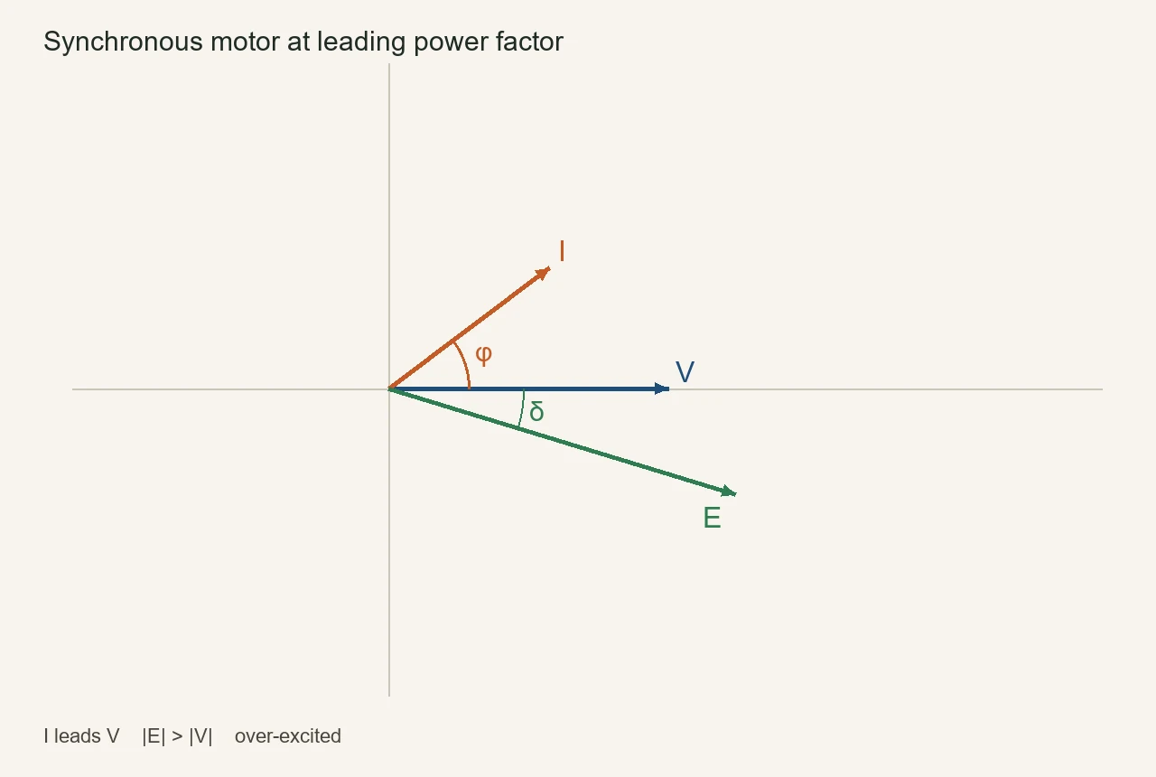
A phasor diagram of synchronous motor at leading power factor shows armature current sitting ahead of terminal voltage, with internal voltage drawn longer than the bus, so the machine looks capacitive while it still takes real power for the shaft.
That is the power factor of synchronous motor when field current is past the unity point. The sketch is a per-phase reading tool, not a 3 phase power factor correction circuit diagram and not a meter how-to for lead versus lag.
The rest of the page names V, I, E, and φ, builds the diagram from the equivalent circuit of synchronous motor, keeps δ off the power-factor angle, then marks when an LV cabinet is the plant drawing instead of a machine phasor.
What the Leading-PF Phasor Is Actually Plotting
A leading-PF synchronous-motor phasor is a per-phase snapshot of terminal voltage, armature current, and internal voltage from the motor equivalent circuit, not a panel wiring diagram.
The phasor diagram of synchronous motor at leading PF freezes those three arrows at one instant of the AC cycle. Terminal voltage V / Vt is the usual reference on the +x axis, and armature current I / Ia is drawn into the motor.
Internal voltage E / Ea / Ef is the rotor-field voltage that teaching notes also call back EMF or excitation voltage.
A mill engineer who opens an exam figure is looking at those three arrows, not at a capacitor-bank schematic. The wiring of an APFC panel is a different page.
Synchronous reactance Xs is the inductive drop used to close the triangle. Armature resistance is often drawn small or omitted, because the geometry that matters is still V, I, and E.
How to Read V, I, E, and φ on the Leading-PF Diagram
On a leading-PF sketch, I sits ahead of V by φ, E is drawn larger than V, and that geometry is the over-excited / capacitive case.
Start with φ: that opening between V and I is the power-factor angle. Leading means current peaks before voltage, so I is rotated counter-clockwise from V on the usual plot.
| Symbol | What it is | Leading-PF reading |
|---|---|---|
| V / Vt | Terminal voltage V / Vt at the stator | Reference arrow, usually along +x |
| I / Ia | Armature current I / Ia into the motor | Ahead of V by φ |
| E / Ea / Ef | Internal voltage E / Ea / Ef from the field | Longer than V; lags V by δ |
| φ | Power-factor angle φ between V and I | Opening that says “leading” |
| δ | Load / torque angle δ between V and E | Shaft-load geometry, not φ |
| Xs | Synchronous reactance Xs | jIXs sits 90° from I |
Call the same picture over-excitation: extra DC on the rotor raises E until Ea cos δ is larger than Vt. From the bus the motor then looks like a capacitor and supplies vars while it still converts watts to shaft torque.
A 0.8 leading nameplate carries that extra armature and field current. Unity and 0.8 are the common industrial ratings; the 0.8 machine is the one drawn to stay on the leading side under load.
Speed stays locked to line frequency. Raising field current swings I and E. It does not make the motor faster.
How to Construct the Diagram from the Motor Equation
Draw V on the +x axis, draw I leading V by φ, add the IaRa and jIaXs drops, then close the triangle to E.
The equivalent circuit of synchronous motor writes the per-phase loop with current into the machine: V = E + I(Ra + jXs). Rearranged, E = V − IRa − jIXs. Keep one current direction for the whole drawing.
- Place V along +x.
- Place I ahead of V by the known leading angle φ.
- Draw IRa in phase with I. It is usually short.
- Draw jIXs 90° ahead of I.
- The far end of that drop chain is V, so the remaining arrow from the origin is E.
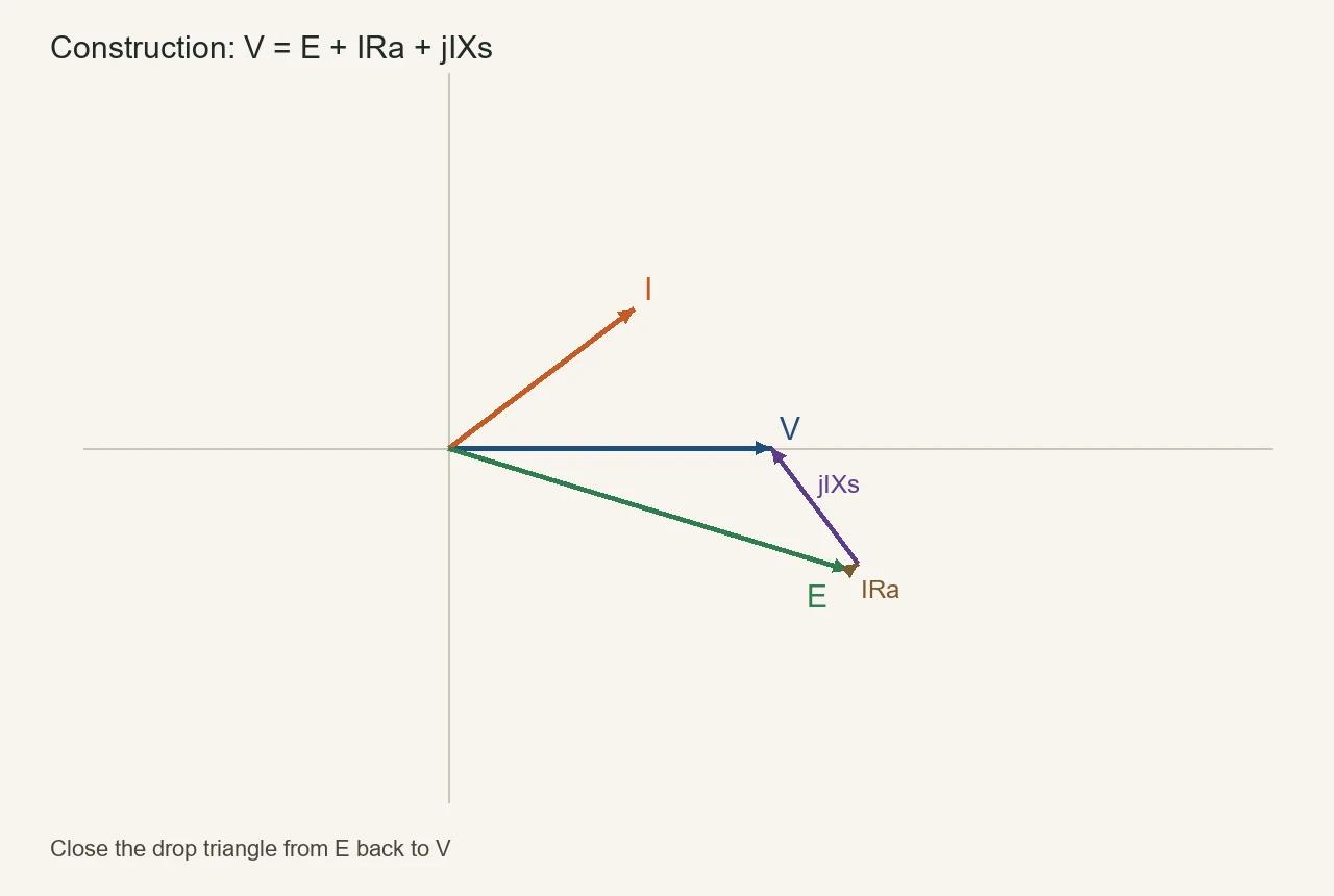
If the current arrow is flipped mid-drawing, the same numbers produce a generator figure. That is a reference choice, not a new machine.
Electrical Academia keeps the motor current into the terminals and uses Ea cos δ > Vt as the leading / over-excited test. Electrical4U walks the same construction with Vt as the reference.
Why δ Is Not the Power-Factor Angle
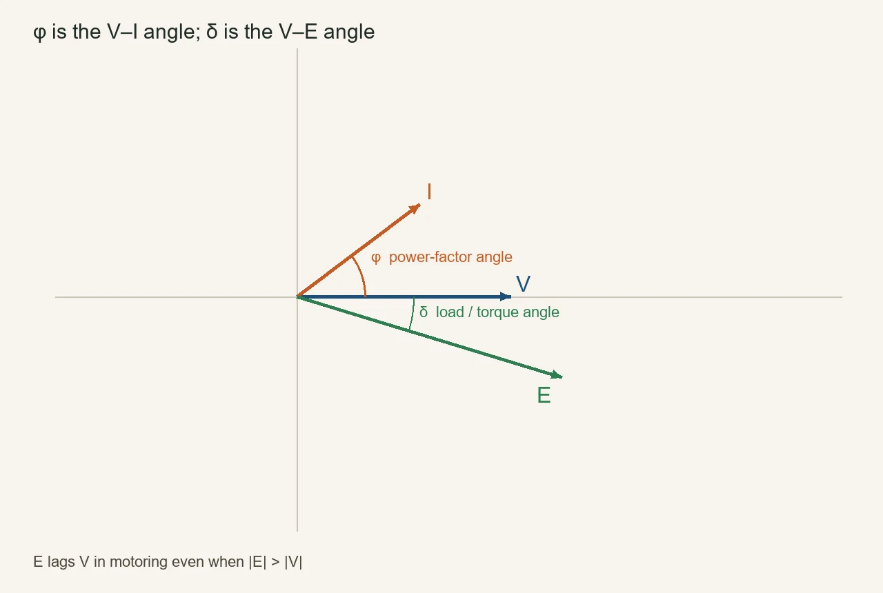
φ is the V–I angle; δ is the V–E angle, and E lags V in motoring even when |E| > |V|.
Load / torque angle δ is how far the rotor field sits behind the bus. In motor convention the internal voltage lags the terminal voltage. That lag is the condition for electrical power into the shaft.
φ can sit on the leading side of V at the same time. The two angles answer different questions: one is “does current lead voltage,” the other is “is this still a motor.”
From the field: A common exam objection is whether Ef > V makes the motor a generator; it does not, because generation is power direction (E leading V, current out of the machine), not the |E| versus |V| comparison. The leading-PF motor still takes watts and supplies vars — see the Electronics Stack Exchange thread.
Andy Knight’s motor notes put the same rule in one line: E lags V when the machine is motoring. The Wikipedia synchronous motor page says motor action when the field poles are dragged behind the air-gap flux.
A zero-shaft special case of the same drawing is the synchronous condenser. E stays larger than V and I leads V by about 90°, so the machine looks like a spinning capacitor. That is still the leading-PF geometry with almost no shaft load.
The live page on over-excited reactive-power wording owns the VAR-flow and generator-language trap. This page stops at the arrows.
How the Leading-PF Diagram Differs from Lagging and Unity
Lagging current sits behind V and marks under-excitation; unity puts I on top of V; leading is the sketch this page owns.
Under-excitation is the other field setting: E is short of the matching value, Ia lags Vt, and the motor draws magnetizing current like an inductor. Unity is the V-curve minimum, where I lines up with V and reactive exchange is near zero.
| Case | Where I sits | What E looks like | From the bus |
|---|---|---|---|
| Leading | Ahead of V by φ | Usually longer than V | Capacitive; supplies vars |
| Unity | On top of V | Matches the unity-PF field | Almost no Q exchange |
| Lagging | Behind V by φ | Usually shorter than V | Inductive; absorbs vars |
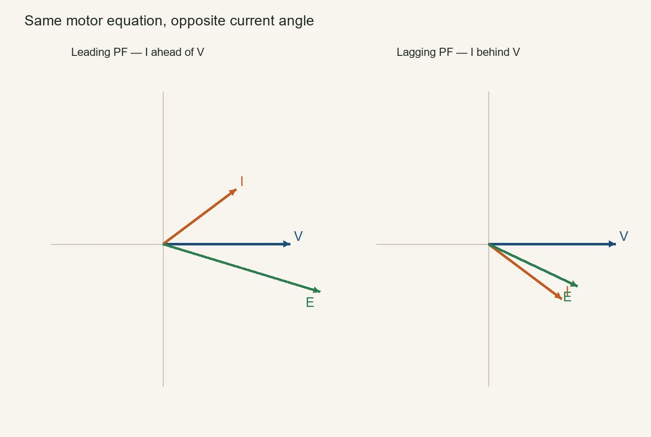
A loaded motor can still show the leading sketch. Plants run compressors and mills at 0.8 leading on purpose. Unloading the shaft slides the same over-excited machine toward the synchronous-condenser picture; it does not flip the current behind V by itself.
Wikipedia’s synchronous condenser article and the power-factor page keep the words straight: leading means current leads voltage.
When This Machine Diagram Is Not Enough — Choose HYTBBJ or HYTBBD
If the plant has no over-excited synch motor, or the field is already at its limit, the useful drawing is an LV APFC cabinet: HYTBBJ for steady inductive demand, HYTBBD when that demand swings.
Most low-voltage rooms are full of induction motors. They do not have a spare synchronous machine sitting on the incoming board, and they cannot “draw φ” into a capacitor they do not own.
Tip: Eng-Tips field notes warn that oversizing a loaded synch motor and pushing field current past the winding rating overheats the field. The diagram can still look leading while the machine is already out of thermal room. That is when a capacitor cabinet, not more excitation, is the next drawing — generator excitation and power factor thread.
The HYTBBJ series low-voltage static reactive power compensation system automatically switches capacitor groups according to measured reactive demand or power factor. It is printed for relatively steady inductive loads in manufacturing, buildings, and public facilities.
The model example sits at 0.4 kV. Switching delay is listed as 0–120 s, with a special fast mode ≤1 s.
A printed feature line says it reduces harmonic current (typ. 20%–30%); treat that as a cabinet feature, not a plant energy-saving claim.
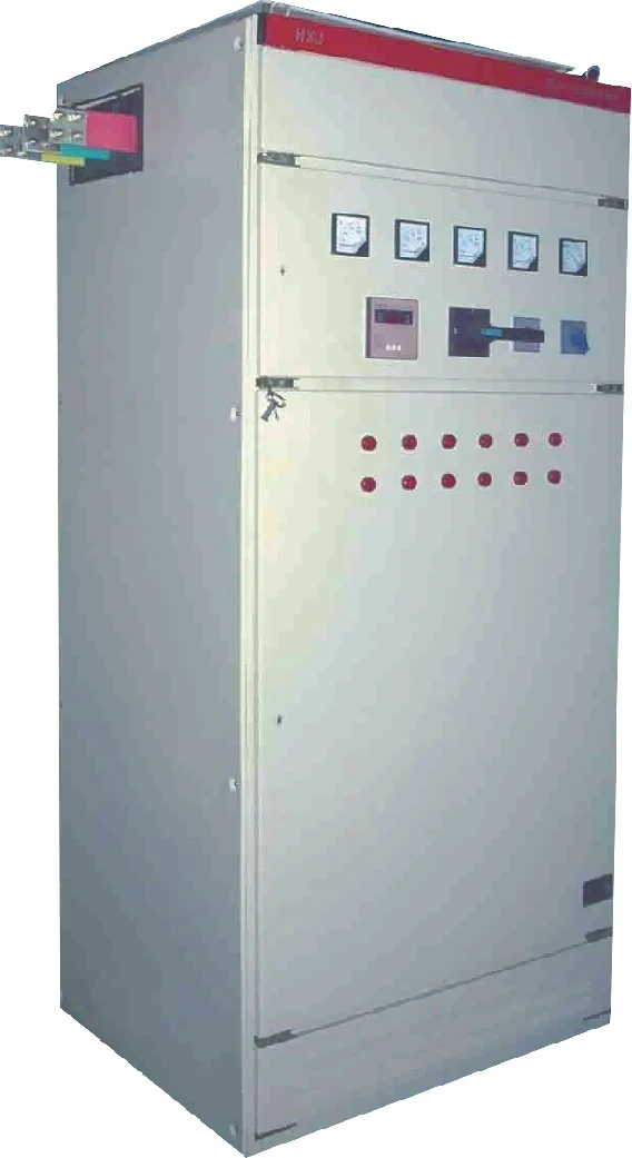
The HYTBBD series is the printed path when inductive load varies — metallurgy, mining, machinery, and similar swinging feeders. The table lists AC380 V ~ AC1140 V ±15%, 50 Hz / 60 Hz ±4%, target power factor ≥ 0.95, and 15–60 kvar per group.
The LV PF compensation hub at Low Voltage Power Factor Compensation Series is the family map for those cabinets, plus outdoor and end-point units. It is not a synchronous-motor catalog.
Do not buy HYTBBJ as a sag restorer or as a substitute for an active filter. The machine phasor told you the motor can look capacitive. The cabinet is what most LV plants actually install when that motor is not on the floor.
FAQs
What is a phasor diagram of a synchronous motor?
It is a per-phase plot of terminal voltage, armature current, and internal voltage from the motor equivalent circuit. The arrows show phase, not a panel wiring layout.
How do you read a phasor diagram of a synchronous motor at leading power factor?
I leads V by φ, E is larger than V, and the motor looks capacitive. That is the over-excited reading of the same sketch.
How do you construct the leading-PF diagram?
Put V on +x, draw I ahead of V, add IRa and jIXs, then close to E. Keep current defined into the motor for the whole drawing.
What is the difference between φ and δ on the diagram?
φ is the angle between voltage and current. δ is the angle between voltage and internal voltage, and E lags V while the machine is motoring.
Does Ef > V mean the motor has become a generator?
No. |E| > |V| is the over-excited test. A generator is a power-direction / current-reference statement, not a length comparison.
How does the leading-PF diagram differ from lagging or unity?
Leading puts I ahead of V. Lagging puts I behind V. Unity parks I on V at the V-curve minimum.
Can a loaded synchronous motor still show a leading-PF phasor?
Yes. A 0.8 leading nameplate exists so the motor can stay leading while it still turns a shaft.
When is an LV capacitor cabinet the better drawing than this phasor?
When the plant has no over-excited synch motor, or the field is already at its thermal limit. Then HYTBBJ or HYTBBD is the printed LV path.
References
- Electrical Academia — Synchronous Motor Equivalent Circuit and Phasor Diagram
- Andy Knight — Synchronous motor notes
- Wikipedia — Synchronous motor
- Wikipedia — Synchronous condenser
- Wikipedia — Power factor
- Electrical4U — Phasor Diagram for Synchronous Motor
- Electronics Stack Exchange — Synchronous Motor Leading Power Factor
- Eng-Tips — Generator Excitation and Power Factor