
 Zhejiang Hongyan Electric Co., Ltd.





































how to size a capacitor bank starts as a selection workflow: collect operating data, turn the required kvar into fixed or switched stages at the right voltage class, decide whether the bank stays plain or detuned, then package those choices so an RFQ can be checked.
In plant language, capacitor bank sizing is that selection plan—not a calculator printout alone. The classic tanφ walkthrough that turns kilowatts and power-factor targets into Qc lives on how to calculate kvar for capacitor bank; nameplate rated-versus-effective kvar arithmetic lives on how to calculate kvar rating of capacitor bank.
Enclosure and protection design choices sit on the capacitor bank design guide. A multimeter field check is a separate verification step after the size plan exists. This article owns the size plan itself—data, stages, architecture, and the RFQ package—not a trig tutorial.
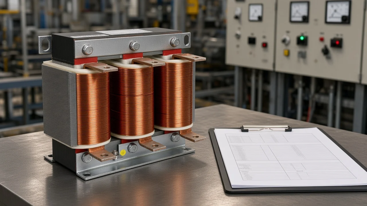
Data to Collect Before You Size a Capacitor Bank
Collect representative active power and power factor at the correction point, a realistic target power factor, voltage class, load profile, and harmonic indicators before you lock any kvar total.
A size plan fails when it starts from connected-load nameplates alone. Peak connected kilowatts ignore lunch breaks, night shifts, and weekend minima—the exact moments when a fixed capacitor bank can push the bus leading.
Industrial sizing guides stress load-profile analysis for the same reason: the bank must correct the demand the meter actually sees, not the sum of every motor plate in the plant.
Use this data-to-collect table before you treat Reactive power (Qc / kvar) as final.
| Data item | What to capture | Why it changes the size plan |
|---|---|---|
| Active power at correction point | Representative kW (or demand window the tariff uses) | Sets the scale of Qc |
| Existing power factor | Bill, meter, or logger displacement PF at that point | Sets how much lagging reactive power you start with |
| Target power factor | Tariff threshold plus a small lagging margin | Typical industrial aims sit near 0.95–0.98 lagging—not unity by default |
| Voltage class / bus range | Nominal bus and expected continuous range | Locks can voltage and effective kvar language |
| System frequency | State as 50 Hz or 60 Hz when ratings depend on it | Keeps µF/nameplate conversions honest when needed |
| Load profile | Min / typical / peak, shift pattern, seasonal change | Decides fixed vs switched and step height |
| Harmonics / nonlinear load indicators | VFD, rectifier, UPS, welder share; any known spectrum | Triggers plain vs detuned architecture |
| Correction location | Service entrance, MCC, motor terminals, or mix | Changes whether one bank or split stages fit |

Write the target as a lagging band unless the utility or a system study says otherwise. Community learners often struggle when a textbook forces a leading destination; plant practice treats leading as a risk of voltage rise and overcorrection, not a default goal.
How Required kvar Rolls into Steps and Stages
Treat required kvar (Qc) as the reactive budget, then split it into a fixed base and/or switched steps that match how the load actually moves.
Qc itself comes from active power and the change in power-factor angle—the calculation spine covered on the kvar-for-capacitor-bank guide linked above. Once that budget exists, sizing work is architectural: how much stays always connected, how much steps with a power factor controller, and how large each click may be.
A practical roll-in sequence looks like this:
- Confirm Qc against measured demand windows, not only a single peak snapshot.
- Cap any fixed portion at the reactive demand that remains almost continuous—often the quiet-plant floor—so light-load leading PF is unlikely.
- Put the remaining budget into switched steps whose smallest stage can follow normal load changes without hunting.
- Round the total and the step list to practical commercial ratings, then re-check power factor at minimum and peak states.
Important: Oversized steps are a sizing failure mode, not a controller mystery. Educational APFC notes warn that oversized stages raise hunting and transient risk when the controller cannot settle (Electrical Notes — Optimum step size selection guidelines). Size the step list to the load change you expect, then let the controller hold a lagging band.
Educational APFC notes often place the smallest step near about 5–10% of the panel’s overall kvar rating as a starting heuristic. Treat that as a rule of thumb, not a code: fine processes and weak controllers need finer steps; slow base-load plants can use coarser stages.
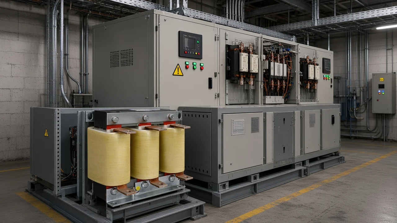
Size Decision Matrix: Fixed vs Stepped and Plain vs Detuned
Choose a fixed bank for steady load, a stepped automatic bank for variable load, and a detuned (reactor + capacitor) architecture when nonlinear or harmonic risk makes plain cans unsafe.
IEEE topic material on shunt power capacitors notes that automated switched banks switch in under heavy load and out under light load to avoid leading power factor and the resulting voltage rise.
Independent sizing references add a common transformer-relative heuristic: when required Qc is only a small fraction of supply transformer kVA—often discussed around the 15% line—fixed compensation may fit; above that level, an automatic / switched bank is usually preferred for variable plants. Use the heuristic as orientation, then confirm against your measured min/max reactive demand.
| Decision | Prefer when | Avoid when | Size-plan note |
|---|---|---|---|
| Fixed bank | Nearly constant load, long continuous duty, small continuous reactive floor | Large day/night swings, frequent light-load intervals | Cap fixed kvar at continuous reactive demand |
| Stepped / automatic bank | Variable MCC or multi-shift load that must hold a PF band | You lack a controller plan or step list matched to load change | Publish step kvar list and min/max verification states |
| Plain capacitors | Low nonlinear share, low resonance concern after screening | Significant VFD/rectifier content or known harmonic amplification | Still verify fuse/thermal duty after sizing |
| Detuned (capacitor + series reactor) | Harmonic-rich bus where plain cans can amplify distortion | Linear steady bus with no harmonic driver | Reactor presence becomes part of the size package; capacitor voltage class rises |
APFC assemblies are often described in three practical families—standard (plain), detuned, and filtered—because the reactor decision changes both the hardware list and the kvar language suppliers must quote. That is a sizing architecture choice, not a reason to rewrite a full enclosure checklist here.
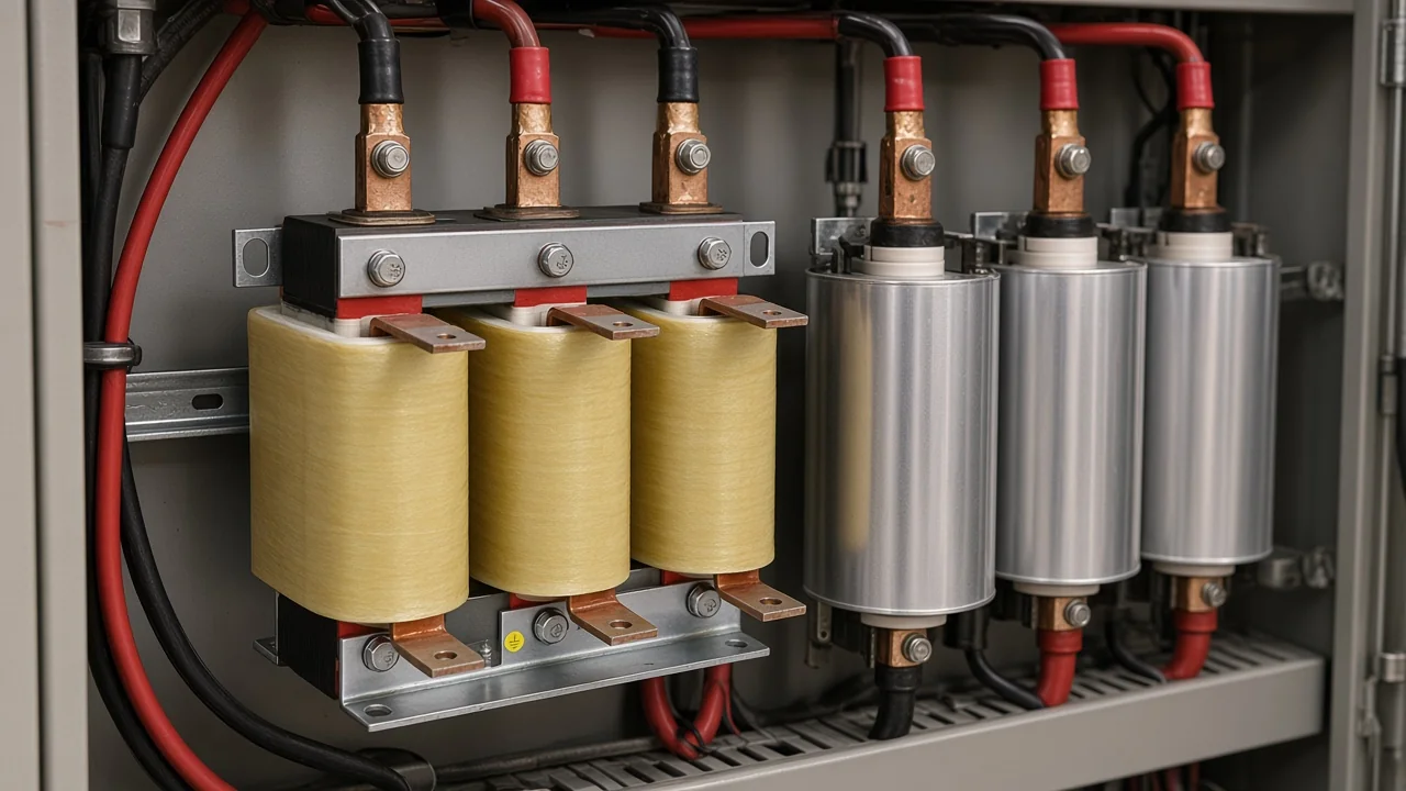
Voltage Class and Frequency Choices in the Size Plan
Lock bank and capacitor voltage to the real bus—and to the rise that appears across a series reactor—before you freeze kvar totals.
When the plan is detuned, the reactor voltage drop raises the voltage across the capacitors, so the can voltage rating must sit above the nominal system voltage. That higher voltage class is part of the size decision, not an afterthought for the purchasing clerk.
Frequency belongs in the same lock file. If a µF conversion or a nameplate frequency differs from the supply, write the system frequency explicitly as 50 Hz or 60 Hz. Do not leave a bare frequency token in the package that a reviewer cannot interpret.
When you need to convert nameplate kvar into what the bus actually sees, use the dedicated rating guide linked in the opening. Keep that arithmetic out of this size-plan article so each page owns one buyer job.
Medium- and high-voltage family options after the size language is clear sit on the High Voltage Power Factor Compensation Series hub.
Build an RFQ-Ready Capacitor Bank Size Package
Package total kvar, the step list, fixed-versus-switched architecture, voltage class, plain-versus-detuned choice, and the load states you will use to verify power factor.
An RFQ that only says “200 kvar capacitor bank” invites mismatched quotes. Two suppliers can both ship 200 kvar and still disagree on fixed versus automatic stages, whether reactors are included, and which capacitor voltage class sits behind a detuned branch.
The size package is the written decision record that makes quotes comparable.
Minimum fields for an RFQ-ready size package:
- Correction point and voltage class (bus nominal and continuous range)
- System frequency stated when ratings depend on it (match the frequency lock already noted above)
- Existing and target power factor (lagging band)
- Required Qc and the measured demand window used to derive it
- Total bank kvar and commercial rounding note
- Fixed base kvar (if any) and switched step list (kvar × count)
- Architecture: fixed only / automatic stepped / combination
- Plain vs detuned (or filtered) — and reactor reactance or tuning notes if detuned
- Capacitor voltage rating assumption, especially for detuned rise
- Verification states: minimum load, typical production, peak demand
- Ambient / altitude envelope the size assumes
From the field: Round the calculated budget to a practical commercial step set, then prove the resulting power factor at every important load state before you freeze the package (EEVblog beginners thread on power factor correction). A neat Qc on a calculator is not yet a size you can buy safely.
Soft next reading for enclosure, switching devices, and protection coordination remains the design guide linked above—after this package locks the size architecture.
When Filter Reactors Fit a Detuned Capacitor Bank Size Plan
Filter Reactors fit when the size plan chooses series reactors with capacitors to form detuned or filter branches on a harmonic-rich bus.
Filter Reactors on the CHYN Power Quality Components line include Filter Reactors (LKSG) dry-type iron-core units intended to sit in series with power capacitors. The live product description states that they form LC resonant branches in harmonic filtering cabinets, present inductive impedance at designated harmonic frequencies, and help absorb local harmonic currents while supporting power-factor improvement in polluted networks.
Published ranges include rated current from 1 A to 1000 A, system voltages such as 280 V, 400 V, 525 V, 690 V, and 1140 V, and matching capacitor capacity from 1 kvar to 1000 kvar.
That product scope matches a detuned size decision: once the matrix chooses reactors, the RFQ must name reactor capacity, voltage, and reactance percentage alongside capacitor kvar and voltage class. It does not match a plain fixed bank on a linear, steady load with little nonlinear content—and it does not replace a harmonic study or the design guide’s enclosure work.
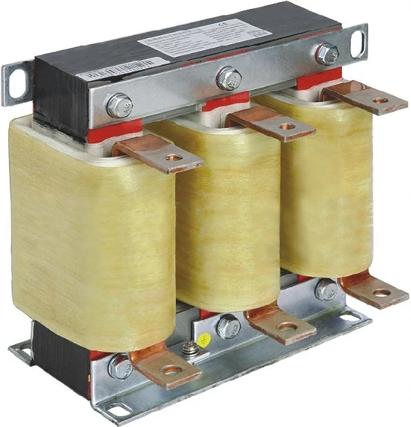
Browse the Power Quality Components hub for adjacent LV building blocks, then open the Filter Reactors page to match voltage, capacity, and reactance notes to the detuned size package. Send bus voltage, step list, and harmonic context only if you need a configuration check—keep that soft hand-off inside this section, not as a separate enquiry workflow.
FAQ
What data do I need before I size a capacitor bank?
You need representative kW and power factor at the correction point, a target PF band, voltage class, load profile (min/typical/peak), harmonic or nonlinear indicators, and the intended correction location. Without that set, Qc is only a guess.
How is sizing different from calculating kvar with the tanφ formula?
The formula gives the reactive budget. Sizing turns that budget into fixed or switched stages, voltage class, plain or detuned architecture, and an RFQ package. Use the kvar calculation guide for the tanφ walkthrough; use this page for the selection plan.
Should I choose a fixed or automatic bank?
Prefer fixed when load is nearly constant and the continuous reactive floor can absorb the bank without light-load leading PF. Prefer automatic stepped banks when load swings across shifts or production cycles and you must hold a PF band.
How large should each switched step be?
Match step height to the load change you expect. Educational APFC guidance often starts near 5–10% of total panel kvar for the smallest stage; oversized steps are a common cause of hunting and over/under-correction.
When does a size plan need detuned reactors?
When nonlinear loads or known harmonic content make plain capacitors likely to amplify distortion or overload. Detuned architecture adds series reactors and usually a higher capacitor voltage class to the size package.
What belongs in an RFQ-ready size package?
Total kvar, step list, fixed/switched architecture, voltage class, plain vs detuned notes, verification load states, and frequency when ratings depend on it. A single “kvar only” line is not enough for comparable quotes.
Should I size to unity power factor?
Usually no. Industrial practice targets a lagging band such as about 0.95–0.98 unless a tariff or study requires otherwise. Unity or leading targets raise overcorrection and voltage-rise risk on light load.
How does voltage class affect the size plan?
Bank and capacitor voltage ratings must match the bus—and the higher voltage that appears across capacitors in a detuned branch. Wrong voltage class changes delivered kvar and stress even when the kvar number looks correct.