
 Zhejiang Hongyan Electric Co., Ltd.





































A de-energized capacitor bank can be screened with a handheld digital multimeter, but only after you prove the stage is discharged. how to check capacitor bank with multimeter work starts with isolation and zero-energy verification, then capacitance or coarse continuity checks against the nameplate—skip live power-factor readings on the same tool. The sections below cover capacitor bank testing safety, how to measure capacitance with multimeter modes on isolated stages, pass/fail interpretation for power factor correction capacitors, when to escalate beyond a DMM, and when a modular LV filter/compensation step is a fit replacement.
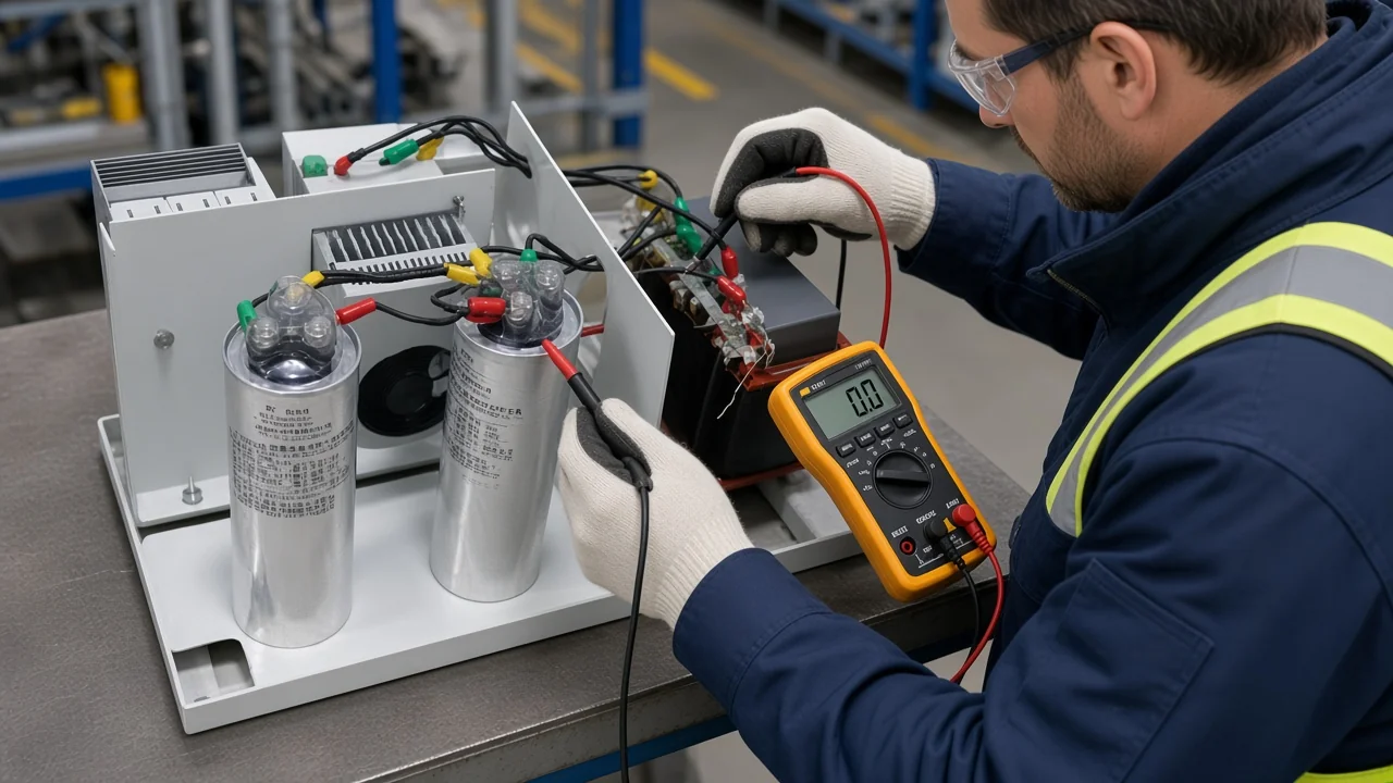
Discharge and Prove Zero Energy Before Any Multimeter Check
De-energize the bank, wait the manufacturer discharge window, apply an approved discharge method, then confirm zero residual voltage with a suitably rated meter before any capacitance or continuity work.
Capacitor banks store energy after the feeder opens. A failed internal discharge path can leave dangerous residual voltage even when the cabinet looks “off,” which is why grid and utility procedures treat wait time as a design aid—you still need a discharge stick and a meter check. For many IEC-oriented units, discharge networks are designed to bring residual voltage down toward a low safe residual within about ten minutes from peak, but series-connected banks can still show higher terminal voltage after that window—follow the nameplate and the bank manual first.
Practical sequence for qualified personnel:
- Switch the bank out and establish your site isolation / lockout practice.
- Wait at least the manufacturer-stated interval (field notes for medium-voltage banks often cite several minutes as a minimum before grounding work).
- Ground phases and, where applicable, the neutral; individually discharge units with an approved method before contact.
- Confirm with a meter rated for the duty: no AC present, then a DC check phase-to-phase and phase-to-ground. Residual voltage means you are not clear for probing.
Important: Capacitors can deliver a lethal shock long after power is removed, and a failed discharge circuit can leave stored energy for an extended period—confirm zero energy with a properly rated meter before capacitance work. (Troubleshooting power factor correction capacitors — Fluke)
For routine in-service cues after the bank is back online, use the plant’s capacitor bank maintenance playbook; keep the multimeter job for confirmed offline checks.
Multimeter Modes Versus What They Can Prove on a Capacitor Bank
Capacitance mode and coarse continuity help on isolated, discharged stages; a handheld DMM does not measure live power factor or replace a megohmmeter for bank insulation integrity. When teams talk about residual voltage left after switching, they mean the energy still sitting on the cans—confirm it is gone before you trust any microfarad number.
| Meter mode | What a reading can support | What it does not prove |
|---|---|---|
| Capacitance (µF / Farad dial) | Offline microfarad value of an isolated can or stage vs nameplate / manufacturer tolerance | Live kvar delivery, harmonic stress, or controller health |
| Continuity / low ohms | Coarse short screen (near-zero ohms or continuous beep) | Accurate µF, ESR, or dielectric absorption |
| Resistance (higher Ω ranges) | Rough “charges toward open” heuristic on some electronics-style checks | Pass/fail for power capacitors against IEEE-style capacitance bands |
| AC/DC volts (as a safety tool) | Zero-energy verification before other modes | Capacitance health by itself |
| Clamp amps on an energized stage (maintenance context) | Relative stage current imbalance when the controller calls a step in | Capacitance value; still not a PF measurement |
A basic meter without a capacitance function may catch a dead short and little else—community technicians still remind beginners that “value” and “short check” are different jobs. Deep insulation checks between bus and ground usually need an insulation resistance tester; the ohms range on a pocket DMM is the wrong primary tool. For how the bank was first wired into the panel, see capacitor bank installation.
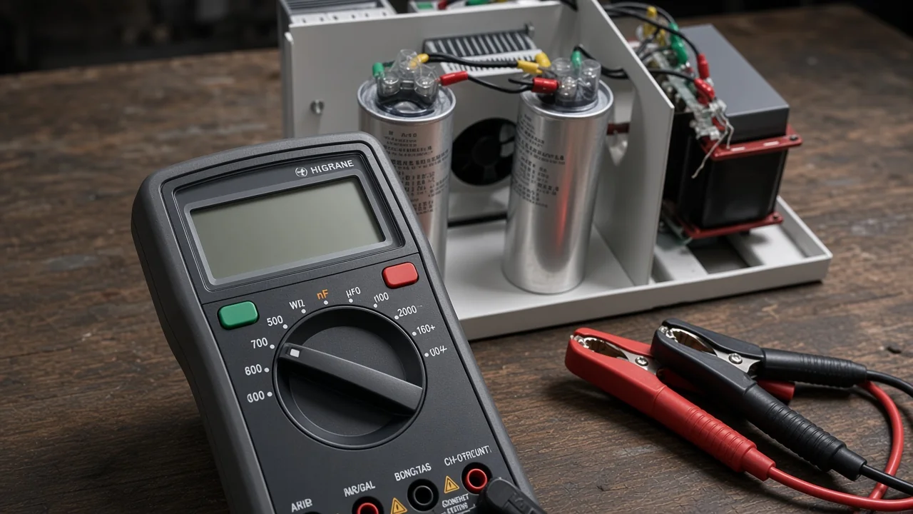
Step-by-Step: How to Check Capacitor Bank Stages with a DMM
Isolate the stage, lift parallel paths when practical, measure capacitance with a stable reading, and log each result against the nameplate before you call the step good or failed.
- Confirm the bank is clear. Complete the discharge and zero-energy steps above. If voltage reappears, stop and re-discharge.
- Identify the stage under test. Note fuse status, contactor position, reactor presence, and the nameplate µF or kvar marking for that can or module.
- Break parallel paths. Disconnect the line-side terminal or lift one side so neighboring cans stop masking the reading. Capacitance bridges used on some MV banks can avoid bushing rework, but a handheld DMM usually needs a clean two-terminal path.
- Set capacitance mode. Use the Farad / capacitance symbol on the dial; many meters also need a function button. Keep leads on long enough for autorange to settle—larger capacitors can take several seconds.
- Record and compare. Write the reading next to the nameplate value and the nameplate tolerance from the OEM sheet. IEEE Std. 18 cites a capacitance rating band of 0 to +10% of nominal for shunt power capacitors; many makers ship tighter bands, so prefer the plate and OEM bulletin when they conflict.
- Optional coarse short screen. Only after capacitance (or afterward if the meter has no µF range): continuity or low ohms. Near-zero ohms that stays near zero is a strong short suspicion; a rising ohms trace alone is still incomplete health proof.
- Restore connections to torque guidance in the OEM sheet before re-energizing. Over-torquing bushings is a known damage path on power capacitors.
Electronics-scale discharge examples (such as a resistor across small leads for a few seconds) illustrate controlled discharge on small parts. Medium-voltage banks still need rated sticks and the OEM discharge sequence.
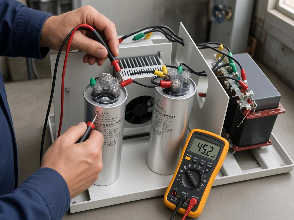
Symptom, Multimeter Reading, and Next Action
Use the meter pattern—open, short, or out-of-tolerance capacitance—to decide whether to retest, replace the unit, or escalate instrumentation.
| Symptom or context | Typical DMM pattern | Next action |
|---|---|---|
| Externally fused can, blown fuse, uncertain can health | Capacitance far above nameplate band, or OL on capacitance | Treat as failed or partially failed; replace after confirming isolation; retest neighbors |
| Internally fused can, subtle capacity loss | Capacitance below nameplate / trending down vs prior log | Log baselines; many OEM notes flag multi-section fuse events—keep historical readings |
| Open / disconnected internal path | Very low capacitance (near nF floor) or “discharge” style display codes on some meters | Replace; inspect wiring and fuse links |
| Dead short | Capacitance OL on some meters, or near-zero ohms on continuity | Replace; investigate what stressed the stage (heat, harmonics, wrong duty) |
| Reading looks “perfect” with cans still paralleled | µF close to the sum of several units | Lift one side and retest—parallel paths fake healthy stages |
| Meter hangs or OVERRANGE on large µF | No stable number after a long wait | Confirm discharge, check meter range, or use a capacitance bridge / LCR suited to the size |
| Insulation concern after cleaning / moisture | DMM ohms inconclusive | Use an insulation resistance tester per the bank procedure, then re-discharge |
Keep a stage log. Internally fused designs can lose only a few percent of capacitance per failed section while temperature and meter accuracy also move readings a similar amount—without history, early failure is easy to miss.
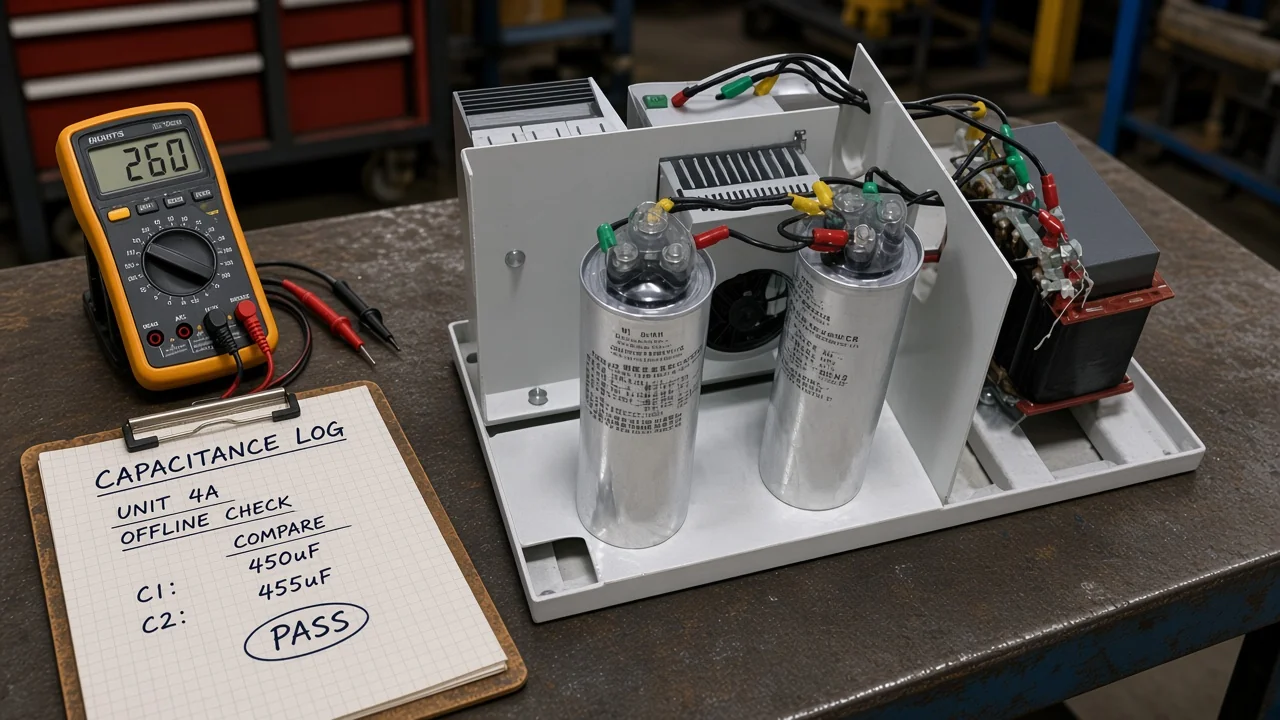
When a Multimeter Is Not Enough for Bank Health or Power Factor
A DMM cannot replace a power-quality analyzer for live power factor, and it is the wrong primary tool for deep insulation or harmonic resonance decisions.
Measuring power factor needs simultaneous voltage, current, and real power over time. Instrument makers state plainly that a digital multimeter cannot perform those measurements; a power-quality analyzer or logger with proper clamps can. Plant threads that ask “can I check PF with only a multimeter?” usually end the same way: you need watts and VA, not ohms and µF alone.
Escalate beyond a handheld DMM when:
- The complaint is utility PF penalties, leading/lagging swings, or “the bank does nothing on the bill.”
- Harmonic alarms, reactor overheating, or resonance suspects appear—detuning and filter decisions need spectrum evidence, not a single µF snapshot.
- Commissioning calls for high-voltage withstand, tong bridges on MV stacks, or formal insulation resistance programs.
- You are still sizing kvar for a new load—that calculation lives in how to calculate kvar for capacitor bank. Greenfield bank capacity design is a separate sizing exercise.
For HV equipment families and outdoor/indoor bank packages, start from the high-voltage power factor compensation series hub after the measurement plan is clear.
Which Filter/Compensation Modules Fit After a Failed Multimeter Check
Choose modular Filter/Compensation Modules when an LV step fails capacitance or short screening and you need a standardized capacitor-plus-reactor drawer for the cabinet.
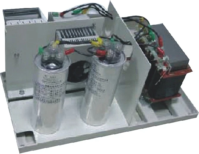
These modules combine capacitors with a series detuned reactor where specified, plus contactors, fuses, busbars, and terminals for low-voltage compensation and harmonic-mitigation steps.
Published options include detuning factors such as 5.67%, 7%, 12%, or 14%; voltage classes such as 400 / 450 / 480 / 525 V; and sectional capacities in the 12.5–50 kvar per unit range, with cabinet dimension tables for 25–100 kvar class assemblies.
That package matters after a failed multimeter check because the “unit under test” in many LV cabinets is already a switched step—the failed asset is often the whole switched drawer, not a lone can on a bench. Harmonics on the bus are why a plain can and a detuned module are different replacement paths after a failed reading.
Fit when: the DMM (or bridge) confirms an open, short, or out-of-tolerance LV stage; the bus has harmonic content that already justified a detuned step; and the cabinet can accept a modular width and bottom-wired drawer.
Skip the module swap when: the real issue is live PF measurement, controller CT wiring, or a kvar target that was never calculated correctly; the failed asset is an MV can that needs specialty HV procedures; or the plant only needs a temporary fuse reset without addressing the failed dielectric.
Match module voltage, detuning factor, and step kvar to the existing controller program and reactor strategy before swapping hardware. The multimeter job ends at “this stage is electrically wrong”; the module decision starts at “what modular step restores the intended compensation path.”
FAQs
How do you test a capacitor bank with a multimeter safely?
De-energize and isolate the bank, wait the manufacturer discharge window, discharge with an approved method, verify zero AC/DC residual voltage, then isolate the stage and measure capacitance or run a coarse continuity screen. Skip live probing.
How can you tell a bad capacitor from a multimeter reading?
Compare µF to the nameplate band. Very low capacitance suggests open; persistent near-zero ohms suggests short; values outside the stated tolerance (IEEE Std. 18 cites 0 to +10% of nominal for many shunt power capacitors) suggest partial failure—direction can differ for internally vs externally fused cans.
Which multimeter mode or symbol is used for capacitance?
Use the capacitance / Farad function (often shared on the dial with another mode and enabled by a function button). Continuity or ohms are only coarse short screens afterward.
Can a multimeter measure the power factor of a capacitor bank?
No. Power factor needs simultaneous real power and apparent power over time. Use a power-quality analyzer or a wattmeter plus proper V/I measurements—not capacitance mode.
Why disconnect a capacitor from the bank before measuring microfarads?
Parallel cans, reactors, and wiring paths distort handheld capacitance readings. Lifting one terminal or removing the unit gives the meter a clearer two-terminal path.
How long should you wait after de-energizing before probing?
Follow the nameplate and manual first. Many designs target a low residual within roughly ten minutes for units (longer for some bank assemblies), but series banks can remain higher—always verify with a rated meter after waiting.
When do you need an insulation tester instead of a DMM?
When the question is bus-to-ground or phase insulation integrity after moisture, cleaning, or commissioning—not when you only need offline µF. Use the IR tester specified for the plant rating, then discharge again before handling.
What should you do after a stage fails the multimeter check?
Replace or rebuild the failed step, recheck neighboring stages, and correct the stressor (heat, harmonics, wrong duty). On LV modular cabinets, a detuned Filter/Compensation Module is often the clean replacement path once the failure is confirmed.