
 Zhejiang Hongyan Electric Co., Ltd.
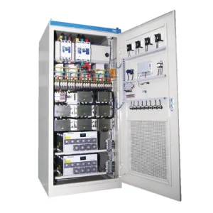
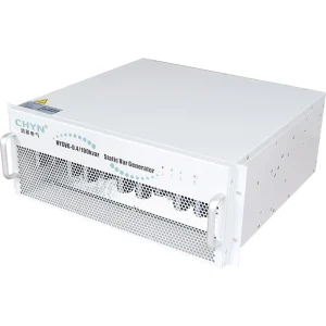

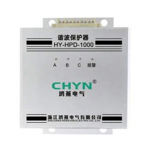
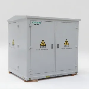
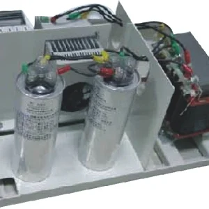
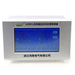
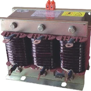
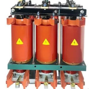
Power factor correction with solar PV must be assessed at the point where the grid, photovoltaic generation, loads, and compensation equipment interact. A PV inverter exporting active power at unity power factor can reduce grid-imported kW while leaving the site's reactive demand largely unchanged. The grid-side power factor can then fall even though imported active energy decreases. The remedy is not to copy the old capacitor calculation using a different kW reading. Measure simultaneous active and reactive power, confirm inverter controls and metering conventions, and coordinate the available compensation across import, low-import, and export conditions.
Why power factor can fall after solar is installed
Consider an industrial site whose motors and other equipment continue to operate at the same load. If a PV system supplies part of the site's active power while contributing no reactive power, the utility supplies less active power but still supplies the remaining reactive power. The ratio between active and apparent power at the utility boundary changes.
This is a change in what the grid connection supplies, not proof that the motors suddenly became less efficient. It also does not prove that the PV inverter is malfunctioning. The inverter may be operating exactly as configured, while the existing compensation controller or original assessment no longer represents the changed power flows.
The IET's article on embedded solar PV and installation power factor describes this distinction between local generation and the installation's grid-side power factor. Keep the measurement boundary visible when interpreting the readings rather than treating every PF value in the plant as the same quantity.
For the fundamental definition and its limits under distorted waveforms, use the electrical engineering power-factor guide. The calculations below use a balanced, sinusoidal or fundamental-frequency model and do not replace a full assessment where harmonics or imbalance are significant.
Draw one power-flow boundary before calculating correction
At a clearly defined grid connection, adopt and document a sign convention. For the illustrative calculations here, imported active power is positive, an inductive site demand is positive kvar, and reactive compensation reduces that demand. Use the actual meter and inverter documentation to translate their displayed signs into this convention.
The simplified relationships are Pgrid = Pload − PPV and Qgrid = Qload − QPV support − Qother compensation. These expressions assume the relevant equipment is inside the chosen boundary and ignore the small differences associated with losses for illustration.
A current transformer measuring only a load feeder will not necessarily describe the same net power as the utility meter after a PV connection is added elsewhere. Establish the physical connection points, sensing points, voltage references, and operating modes from the actual drawing. A good controller cannot correct a boundary it does not measure as intended.
Do not infer leading or lagging behavior from a minus sign alone. Instruments can use different conventions for imported and exported active power and for generator reactive power. Check quadrants, signed kW and kvar, and the documented convention before changing any compensation setting.
A worked example: the load stays the same, but grid-side PF changes
Assume a hypothetical balanced load consumes 200 kW and 150 kvar. With no PV contribution and no other compensation, the apparent power is √(200² + 150²) = 250 kVA and PF is 200/250 = 0.80. Now assume the PV supplies active power at zero reactive output while the same load remains connected.
| Assumed PV active output | Grid active import | Grid reactive demand | Calculated grid PF magnitude |
|---|---|---|---|
| 0 kW | 200 kW | 150 kvar | 0.800 |
| 100 kW | 100 kW | 150 kvar | 0.555 |
| 150 kW | 50 kW | 150 kvar | 0.316 |
The table uses PF = P/√(P² + Q²) for the stated import cases. These are calculated examples, not site measurements or expected CHYN product results. They show why using a reduced grid-import kW value without the corresponding kvar measurement can lead to a misleading diagnosis.
Near zero active import, the PF number becomes a poor standalone control or procurement signal. Export introduces additional direction and quadrant considerations. Examine the underlying power flows and the governing connection requirements rather than trying to make every low-import PF display resemble a full-load reading.
Calculate a target from simultaneous measurements
For a simplified positive-import case with a target lagging fundamental power factor PFt, the corresponding target reactive import is Qt = Pgrid × tan(arccos(PFt)). The indicated additional capacitive correction is Qgrid − Qt, provided the assumptions, signs, boundary, and desired operating direction are appropriate.
Using the 50 kW and 150 kvar example, a hypothetical target of 0.95 corresponds to about 16.4 kvar of reactive import. The calculated correction would be about 133.6 kvar under those specific conditions. This is not a bank-size recommendation: other load levels, nighttime conditions, PV operating modes, export conditions, and available step combinations can require a different response.
Use time-aligned measurements. A daytime kW snapshot combined with a nighttime kvar reading is not a valid operating point. Likewise, a monthly energy ratio and an instantaneous demand reading answer different questions. Identify the relevant measurement and assessment period with the responsible utility or project engineer.
Can the PV inverter provide the required reactive power?
Some inverters offer reactive-power or power-factor control, but capability and permission are separate questions. The supported modes, current limits, priority rules, temperature, voltage, and available apparent-power capacity determine what can actually be delivered. The approved grid-connection requirements determine how those functions may be used.
As an ideal apparent-power illustration, an inverter with rating S and active output P has a remaining magnitude limit Q = √(S² − P²). A hypothetical 100 kVA converter producing 90 kW has an ideal remaining reactive magnitude of about 43.6 kvar. The actual permitted envelope can be more restrictive and can change with operating conditions.
EPRI's OpenDSS PV inverter documentation distinguishes inverter kVA, power-factor, kvar, and priority settings within its model. Model settings are not a statement of a particular installed inverter's capability. Obtain the actual inverter documentation and confirm whether reactive operation remains available when PV active production is low or absent.
Write a control-responsibility matrix showing what each inverter and compensation device is permitted to regulate, at which measurement point, and with which priority. Include saturation, low-production, and loss-of-communication behavior. A shared reactive target is not enough if two controllers independently chase different signals or use different conventions.
Coordinate capacitors, SVG support, and inverter controls
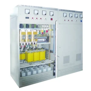
An existing capacitor bank can still be useful, but check its sensing boundary, step sizes, controller modes, minimum-load behavior, and harmonic suitability. A bank sized for a historical operating pattern may not follow the new grid-side demand as solar output and site load change independently.
Fixed capacitive support also needs a light-load assessment. If connected compensation exceeds the required reactive support during a different operating state, the site can move into leading operation. Evaluate daytime, nighttime, low production, maintenance, and credible alternative supply conditions before assuming the original bank can remain unchanged.
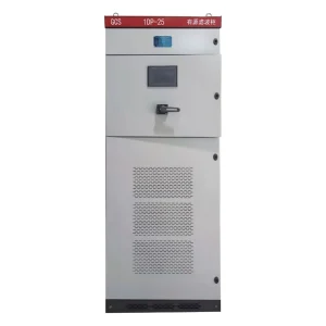
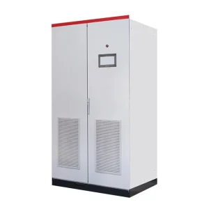
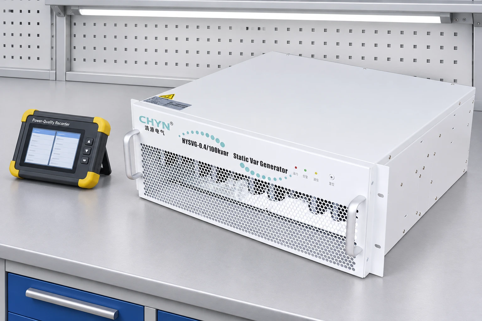
An SVG may be relevant where the required reactive current varies continuously or changes direction, within the selected model's operating envelope. CHYN's HYSVG product family provides a route for that discussion. Submit the measured power-flow profile and required control boundary rather than requesting a size from the PV array's DC nameplate alone.
Harmonic filtering is a separate duty. The SVG versus active harmonic filter comparison explains why a reactive-current target and a harmonic-current target should be stated independently. Solar generation does not make a capacitor bank or an SVG a universal solution for every waveform problem.
Validate the controller across changing power-flow states
Record what happens as PV production rises, cloud cover changes, site load falls, and the grid connection approaches zero import or enters export. Check which device controls which measured quantity and how competing priorities are resolved. Use the approved settings and control philosophy rather than adjusting multiple devices independently until a display looks acceptable.
Acceptance should include grid-side signed kW and kvar, the relevant PF calculation, voltage, harmonic measurements where required, device current limits, and the actual compensation state. Compare similar operating states before and after the work. A favorable result during one midday snapshot does not demonstrate satisfactory operation over the required range.
The broader renewable-energy grid-connection solution overview provides application context. The installation's approved drawings, inverter capability information, and utility requirements remain the controlling project evidence.
RFQ checklist for solar-related power-factor correction
- Provide the one-line diagram showing the utility connection, PV connection, loads, compensation, transformers, and sensing locations.
- Attach simultaneous signed kW and kvar profiles, PF definitions, voltage, harmonic data, and operating-state descriptions.
- State the inverter models, available control modes, documented capability envelope, priority rules, and approved connection settings.
- Describe existing capacitor steps or SVG equipment, required control boundary, nighttime duty, export conditions, and future load changes.
- Agree targets, responsibilities, operating states, and acceptance measurements before ordering equipment.
Tariff treatment and connection obligations are site specific. Confirm the actual assessment rules rather than assuming that a lower displayed PF automatically creates a charge or that one compensation setting is valid for every solar installation.
Further learning: power factor and reactive power
NPTEL's “Lecture - 15 Power Factor” explains the electrical background to active, reactive, and apparent power. It supports the calculation principles here without providing project-specific solar inverter settings.
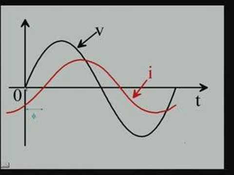
Watch Lecture - 15 Power Factor on YouTube.
Frequently asked questions
Why can grid-side power factor fall after solar PV is installed?
If PV supplies active power while the load reactive demand remains, grid active import falls without a matching fall in reactive import. The grid-side ratio of active to apparent power can therefore decrease.
Should I size compensation from the solar array kW rating?
No. Use simultaneous measured power flows at the intended boundary, the site load profile, available inverter capability, existing compensation, and the required operating states.
Can the PV inverter always provide the necessary kvar?
No. Capability depends on the actual model, available apparent-power capacity, temperature and voltage conditions, priority rules, and approved connection settings.
Does a low daytime PF reading automatically mean a charge or a fault?
No. Confirm the meter convention, active/reactive flows, assessment period, tariff, and connection requirements. Low-import and export states need appropriate interpretation.