
 Zhejiang Hongyan Electric Co., Ltd.
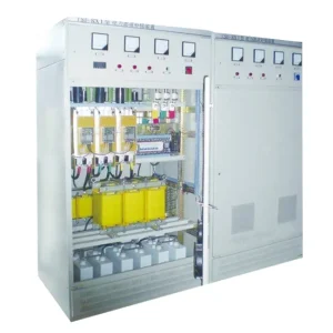
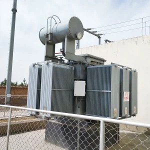
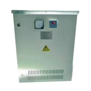
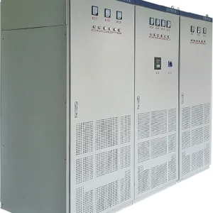
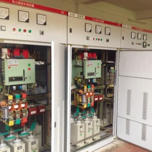
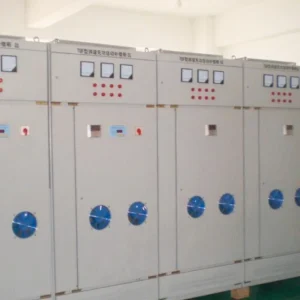
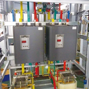
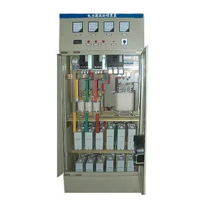
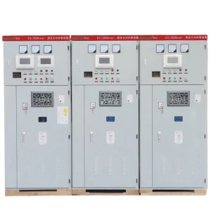
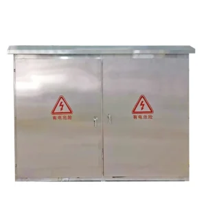
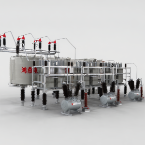
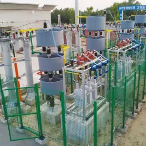
Hybrid reactive power compensation combines a switched capacitor or LC section with a continuously controlled static var generator. The practical selection question is how much steady demand the passive section can carry while leaving enough converter capacity for load changes, light-load operation and credible outages. Specify the sharing rule, measurement boundary and transition tests before choosing a capacity ratio. A larger combined kvar label does not establish that the two sections will cooperate correctly. This guide focuses on coordination and purchase acceptance, rather than repeating a general explanation of harmonic filters or standalone SVG sizing.
Define what the hybrid system must regulate
Start with the electrical location where performance matters. A utility meter, transformer incomer and production feeder may see different reactive power because other loads and compensation equipment lie between them. Put the current transformers and voltage reference on a marked single-line diagram. Define positive and negative reactive power consistently in the controller, recorder and acceptance report.
Then identify the actual objective. Maintaining a billing power factor, limiting reactive exchange at a connection point and supporting local voltage are related tasks, but they can lead to different commands. Agree which objective has priority when they conflict. For a plant with photovoltaic generation, record both import and export conditions; a control rule that works at normal production may behave differently when active import becomes small.
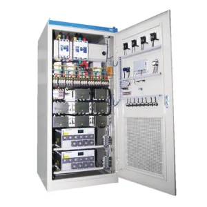
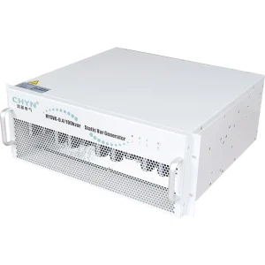
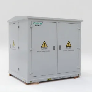
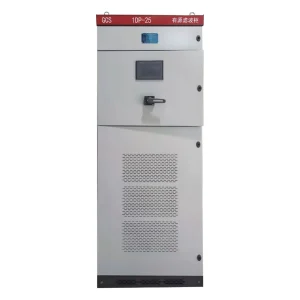
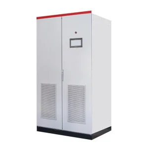
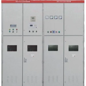
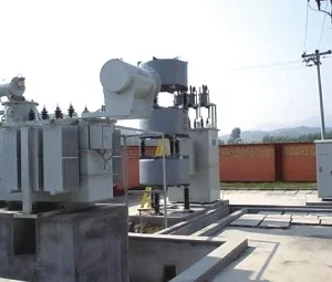
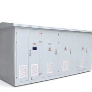
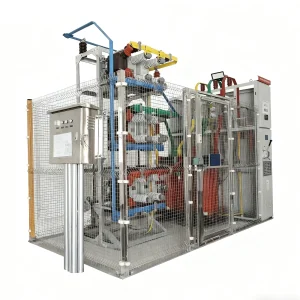
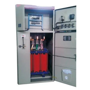
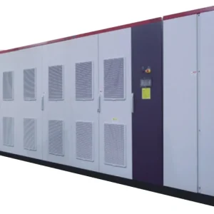
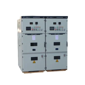
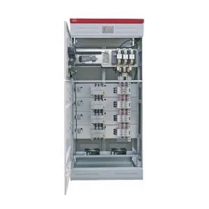
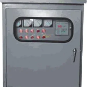
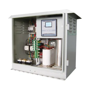
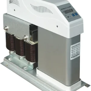
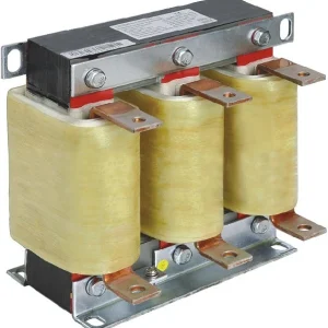
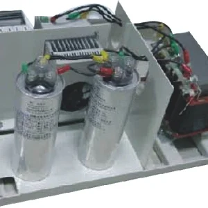
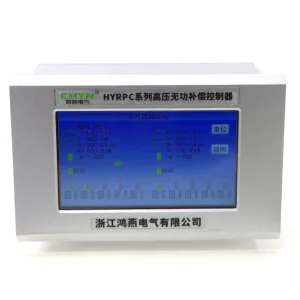
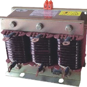
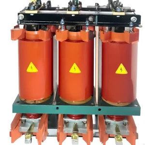
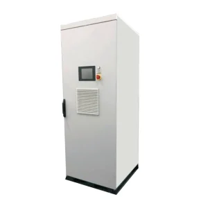
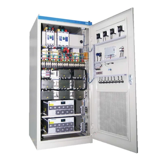
The CHYN HYSVGC hybrid compensation family combines active and passive sections. Its product description establishes the equipment category, not the capacity split or guaranteed results for an unmeasured installation. Ask for a configuration-specific proposal showing the actual modules, branch arrangement, protection and controller functions.
Separate the slow baseline from fast changes
Collect time-aligned active power, fundamental reactive power, voltage and operating-state records across representative shifts. Include production startup, lunch breaks, shutdown and the smallest sustained load. A monthly maximum cannot reveal how much compensation stays connected safely when the process stops. Equally, a slow meter average can hide a short event that uses the converter's available current.
Use the records to identify a baseline that persists long enough for a capacitor step to be useful. Allocate variable demand to the converter only after checking the magnitude and duration of changes. Do not automatically assign every slow change to capacitors: switching restrictions, branch availability, harmonic conditions and voltage limits can keep a nominally available step out of service.
Research on STATCOM operation with a fixed capacitor bank examines combined compensation in a specific grid-connected photovoltaic model. It supports considering the two resources together. It does not establish a universal ratio or demonstrate the performance of a CHYN cabinet.
Specify headroom in both directions
A converter may need to supply inductive-load compensation when demand rises and absorb excess capacitive output when demand falls. Check both directions against its proposed operating envelope. Available reactive capability can change with voltage, current limits, temperature and any additional control duties. State the operating conditions attached to each promised rating.
For an illustrative allocation, suppose a measured load needs 140 kvar of capacitive compensation and connected passive branches deliver 100 kvar at that operating voltage. Ignoring losses and other duties, the converter must supply the remaining 40 kvar. If demand immediately falls to 60 kvar before a branch can open, the converter must instead absorb 40 kvar or the controller must use another permitted action. These values explain the accounting; they are not recommended equipment ratings.
Check the same balance with one passive branch unavailable and with the converter unavailable. Determine whether the site accepts a temporary power-factor deviation, reduced production or disconnection of compensation. Redundancy is an agreed operating outcome, not simply the presence of two technologies in one enclosure.
Write the switching and coordination rules
Require a description of how a branch is added or removed, how the SVG command changes around that event and how the controller prevents rapid repeated switching. Include minimum dwell time, discharge-related closing restrictions, command confirmation and handling of a failed contactor or switching device. Use the selected component documentation to set actual limits.
Two independent regulators can fight if both respond to the same measured error without coordination. A useful supplier explanation identifies the master decision, any subordinate control loop and what happens when communications fail. A statement that the cabinet is intelligent is insufficient for checking these transitions.
For background on unstable step operation, see why an APFC panel hunts between steps. Hybrid control can reduce unnecessary mechanical switching when correctly designed, but adding an SVG does not repair incorrect measurement polarity or an unsuitable switching algorithm.
Use a configuration acceptance table
The following table is a procurement checklist. It sets evidence to request rather than numerical limits. The designer and owner should enter the permitted deviations and response intervals for the actual installation before the order is placed.
| Operating condition | Evidence to request | Decision supported |
|---|---|---|
| Normal production | Shared reactive demand, branch states and SVG current on the same time axis | Whether the proposed baseline allocation works |
| Sudden load rejection | Reactive exchange and branch opening sequence | Whether leading operation is controlled |
| One branch unavailable | Remaining converter margin and alarm response | Whether continued operation is acceptable |
| Converter unavailable | Passive-only operating restrictions and controller fallback | Which loads or steps must be restricted |
| Measurement failure | Fault detection, inhibited commands and restoration sequence | Whether the system enters a defined safe state |
Keep harmonic assessment separate from kvar sharing
A reactive-power balance does not prove acceptable harmonic loading. Passive branches change the network impedance, and converter control may allocate current to more than one function. Obtain a harmonic study for relevant source arrangements and branch combinations. Include weak supply, transformer changes and any standby generator mode that the cabinet is expected to serve.
Ask whether harmonic compensation is included in the proposed converter configuration and whether that function reduces reactive-current availability. Do not infer active filtering capability from the word hybrid. Likewise, an LC branch selected for reactive support is not automatically a tuned filter that can absorb an unspecified harmonic spectrum indefinitely.
University-published research on hybrid compensation in weak distribution networks discusses coordinated capacitor and DSTATCOM control in a defined network study. Treat it as background on control objectives; transfer to an industrial site requires its own network model and acceptance evidence.
Verify the complete measurement chain
Before evaluating capacity, verify CT location, phase identification, polarity, ratios and voltage references. Compare a known load change with both the cabinet display and an independent recorder. Inspect the sign of reactive power as well as its magnitude. Wrong measurement direction can make an otherwise capable controller issue the wrong correction.
Document which other capacitor banks, solar inverters and generator controllers can regulate reactive power at the same boundary. Decide how their commands are coordinated or limited. Review SVG CT polarity checks for the measurement issue; the hybrid system adds switching decisions to that same measurement dependency.
Request a repeatable commissioning record
Agree tests before commissioning, then record the initial settings, instrument locations, active branches and process conditions. Use approved load events rather than deliberately creating unsafe disturbances. Capture normal sharing, an available switching transition and permitted fallback modes. A screenshot after the system settles cannot establish what happened during a transition.
Use the same sign convention and recording interval for each test. If performance is unsatisfactory, retain the original trace and identify the changed setting before repeating it. This gives the owner a usable baseline for later expansion, rather than a collection of unrelated final screenshots.
For the broader converter selection process, consult static var generator sizing inputs. Use that analysis to establish converter duty, then check it again after assigning passive steps and fallback requirements. For the underlying principle, the following neutral educational lecture introduces reactive compensation.
Watch the educational lecture on YouTube.
Information to send with an enquiry
Supply the single-line diagram, supply frequency and voltage range, transformer data, representative load records, existing compensation inventory and harmonic measurements. Include the target measurement boundary, allowed leading operation, expected future expansion and any islanded supply modes. Ask the supplier to list missing inputs and assumptions explicitly.
Request a proposed branch schedule, converter operating envelope, loss and cooling information, controller sequence and acceptance procedure. Separate confirmed configuration details from optional functions. A clear enquiry lets competing proposals be compared on the same operating cases and makes later changes to capacity or control responsibilities visible.
Frequently asked questions
Is there a standard capacitor-to-SVG ratio?
No universal ratio fits every load. Use measured baseline demand, load rejection, switching restrictions, converter capability and permitted fallback operation to choose the split.
Can a hybrid cabinet replace a harmonic filter?
Only when the proposed configuration is designed and verified for the required harmonic duty. Reactive compensation capacity alone does not establish filtering performance.
Why must the SVG sometimes absorb reactive power?
Connected passive branches can temporarily exceed load demand. Absorbing reactive power may help manage that condition within the converter's confirmed operating limits.
What is the most useful acceptance evidence?
Use time-aligned measurements of reactive exchange, voltage, converter output and branch states during agreed operating transitions, together with the final settings and supply configuration.