
 Zhejiang Hongyan Electric Co., Ltd.
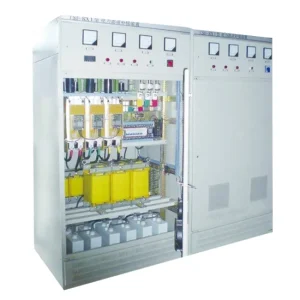
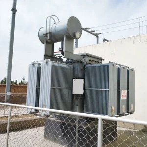
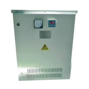
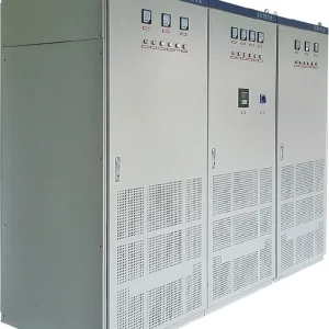
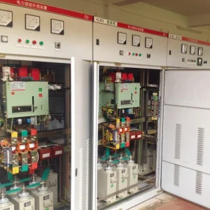
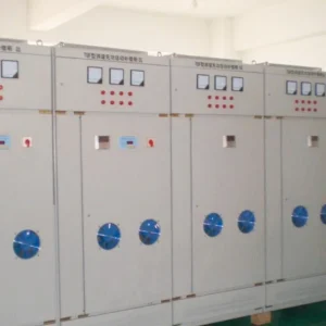
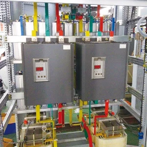
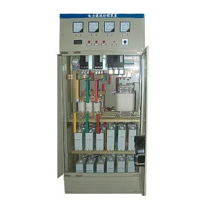
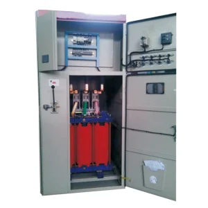
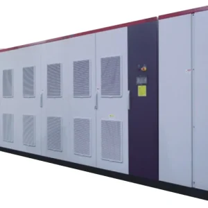
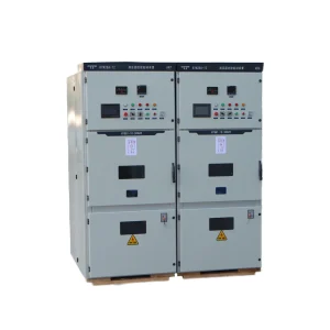
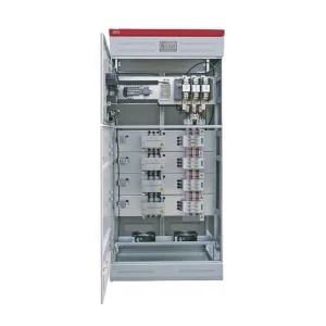
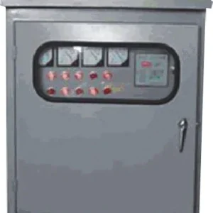
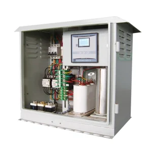
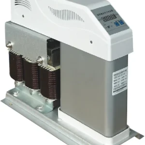
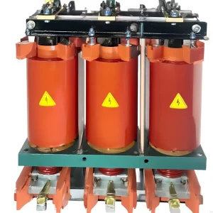
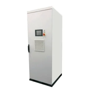
Zero sequence current absorber selection begins with a neutral current survey, not a panel rating. Establish which current components dominate, where they return, and which section of the neutral path needs relief. Then compare those measurements with the offered equipment's supported harmonic orders, continuous duty and behavior in each operating mode. A targeted absorber can be relevant when specific zero-sequence harmonics account for much of the current at the chosen boundary. If fundamental load imbalance, a poor connection or a different return path is the main issue, the evidence may point to a different remedy or to several changes working together.
Map the return path before choosing a measurement point
Mark the transformer secondary, main neutral bus, outgoing panel neutrals, source transfer equipment and the intended equipment location on the single-line diagram. The neutral of a feeder serving electronic loads can carry a different spectrum from the main neutral. Current contributions can also combine differently as they pass upstream. A reduction measured at one point should not be assumed to apply to every downstream conductor. State which segment is the subject of the acceptance test.
Review alternate operating modes with the electrical team. During an outage, a generator, UPS or alternate transformer can change the effective source and neutral path. Record the actual operating arrangement instead of treating backup as a lower-load version of the normal case. Clarify how the offered equipment behaves when the source changes and how it is isolated for service. Changes to neutral and bonding arrangements require review of the existing grounding and protection design.
For background on why these currents occur, see the guide to third-harmonic neutral current. A survey for an equipment decision should go one step further. It needs to show that the component the device can address is present at the point the project is trying to improve.
Measure a spectrum alongside the total neutral current
Have qualified personnel collect time-aligned phase and neutral current measurements under representative loads. Record fundamental and harmonic magnitudes, the relevant phase information if the analyzer supports it, and total RMS current. Note the measurement locations, instrument settings, source, process state and unusual events. Without these records, a short high reading could represent a normal duty, a temporary transfer or a change in the mix of operating loads.
A fundamental neutral component can arise from unequal phase loading. Harmonic components are a separate question. In a three-phase four-wire circuit with a single intended return path, the neutral waveform represents the sum of the phase waveforms, subject to the chosen current sign convention. Equal, in-phase third-harmonic components add in the neutral rather than cancel. In an unbalanced installation, calculate or measure the actual components instead of assuming the simple balanced case applies at every harmonic order.
The ABS guidance on electrical harmonics discusses the significance of harmonics for distribution equipment. Its shipboard context is useful background for interpreting measurements, while the applicable installation requirements and equipment limits must be confirmed for the actual site.
Turn the readings into a duty statement
Consider a teaching example in which the measured neutral components are 24 A at the fundamental, 36 A at the third harmonic and 8 A at the ninth. If these are the only material components, their combined RMS is about 44 A, found from the square root of the sum of their squares. Perfect removal of the third harmonic alone would leave approximately 25 A RMS under unchanged conditions. The example illustrates why total current cannot be subtracted directly from one harmonic magnitude and why targeting the largest component need not remove the entire neutral current.
Define the project objective as both a measurement boundary and a set of load conditions. If the concern is heat, record the loading duration and conditions where the temperature issue occurs, rather than relying on a single current peak. If the concern is a particular harmonic, identify it in amperes and give the measurement interval. Ask the supplier to show the residual current by order and explain which components fall outside the offered equipment's duty.
| Survey observation | Check before requesting a proposal | How it affects the decision |
|---|---|---|
| Third harmonic dominates at one panel | Record its duration, neutral current and upstream contribution | Supports assessment of a targeted device at a stated boundary |
| Fundamental dominates | Compare simultaneous phase loading and return paths | Investigate load redistribution or other causes before assuming harmonic duty |
| Several orders matter | List each order in amperes and request supported duty per order | Reveals whether an alternative or combined approach should be assessed |
| Heat is confined to a termination | Have qualified personnel evaluate connection condition and loading | A current-reduction proposal does not establish that the termination is sound |
| Current changes after source transfer | Compare complete normal and backup operating records | Requires an assessment for both topologies |
Compare options at the same boundary
Different approaches can alter different portions of the measured waveform. Redistribution of single-phase loads may reduce the fundamental imbalance while leaving harmonic content. A suitable four-wire active filter may address a wider combination of harmonic orders and duties. The guides to how an active harmonic filter works and three-wire versus four-wire active filters explain why the connection and current path matter. Compare options against the same measurements, not against different readings from different parts of the installation.
The SeoulTech record for Choi and Jang's neutral-current suppression study describes a tested hybrid topology. It illustrates that neutral-current mitigation can depend on the arrangement of the transformer and converter and on the nature of the load. Its prototype findings cannot be applied as a performance claim for a separate commercial device. Ask each supplier to identify the assumptions used in its own proposal.
Request configuration-specific ratings and behavior
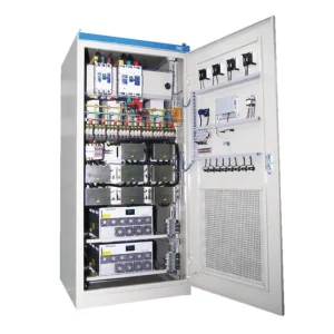
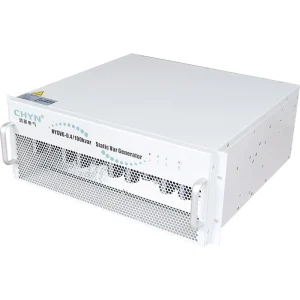
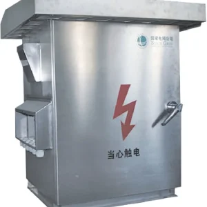
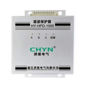
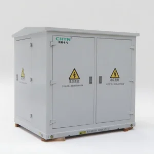
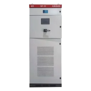
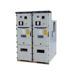
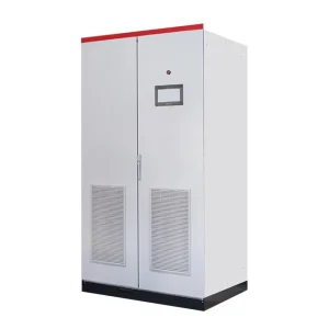
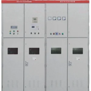
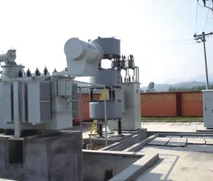
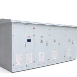
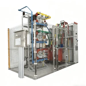
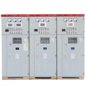
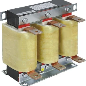
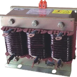
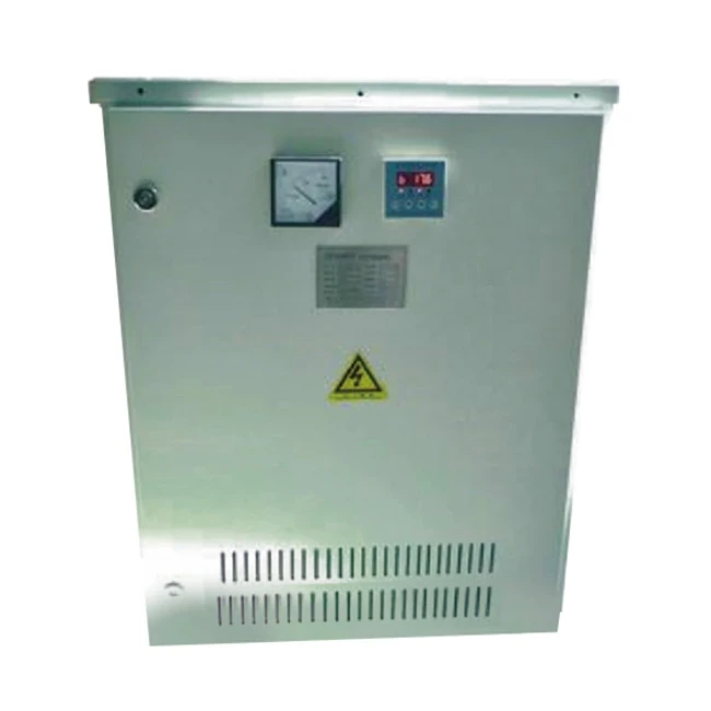
For the CHYN HYLX zero-sequence current absorber, include the one-line diagram, recorded spectra, operating modes and proposed location with the inquiry. Ask which orders the offered configuration addresses, how continuous current is rated, and what happens under overload or when the unit is unavailable. Request the applicable installation drawings and environmental limits. The product photo shows the equipment family and does not establish the electrical characteristics of a specific order.
Also ask how the equipment affects service arrangements. A site may need to keep critical loads operating while a mitigation device is serviced. The electrical team should verify the permitted isolation state, protection coordination and any restrictions on operating with the device out of service. Check how loss of mitigation will be detected, who receives that indication and whether the existing conductors and equipment remain within their approved limits under the applicable operating cases.
Document anticipated load changes separately from the current survey. Installing another row of electronic loads or changing a UPS operating mode can alter both phase loading and harmonic content. Reserve capacity only for stated scenarios, and ask how those scenarios were assessed. A proposed performance figure should identify the measurement point, load mix, supported orders and limits under which it was calculated.
Verify the installation against a matched baseline
Compare the same neutral segment, source configuration and representative load state before and after mitigation. Record total RMS, the targeted harmonic amplitudes and relevant phase and voltage measurements using comparable settings. A percentage improvement is meaningful only with the original and residual quantities alongside it. Add temperature records when temperature was a project concern, allowing for the relevant load duration and thermal conditions.
Investigate an unexpected residual before requesting more equipment. A high fundamental component, unsupported order or remaining current in a downstream segment requires a different investigation from a device that has reached its rated limit. Save the test records, equipment identification and operating conditions so later electrical changes can be compared with the accepted baseline.
Check whether apparent improvement follows the load schedule
Where a facility cycles through different loads, align the comparison with the process rather than the calendar alone. For example, a lower neutral current recorded overnight could reflect a reduction in operating electronic loads even if the mitigation equipment made little difference. Label each test interval with the relevant equipment state and compare repeated intervals when possible. Preserve the spread of readings as well as the representative value so the acceptance record shows how much the duty varied.
If the recorded phase sum and the measured neutral current disagree beyond the expected instrument uncertainty, resolve that discrepancy before treating the numbers as equipment inputs. Check measurement orientation, timing and the single-line diagram with the survey team. An unaccounted parallel path changes the interpretation of what each sensor is measuring and can make a seemingly favorable result at one point misleading.
Further learning
This NPTEL lecture introduces symmetrical components, including the zero-sequence concept used to interpret phase-current measurements. The equipment decision still depends on the actual spectrum and the current paths at the site.
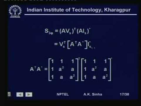
Watch the NPTEL lecture on YouTube.
Frequently asked questions
Can a total neutral current reading size the absorber?
No. Identify the harmonic orders, their magnitudes and the operating cases before checking the offered continuous duty.
Will balancing the phases remove third-harmonic neutral current?
Balancing can reduce fundamental imbalance. Equal in-phase third-harmonic currents can still add in the neutral.
Does an upstream improvement protect every downstream neutral?
No. Check the actual conductor segment and where the current returns. Local currents may persist below the measurement boundary.
Can the same assessment cover backup operation?
Only if it includes the backup source, neutral path and load state. Verify that case separately when its topology differs.