
 Zhejiang Hongyan Electric Co., Ltd.
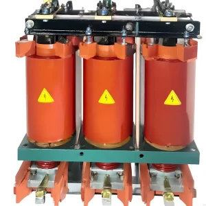
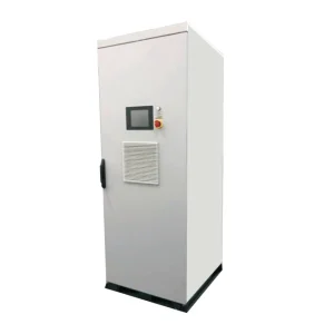
Active harmonic filter CT saturation can corrupt the current waveform that the controller uses to calculate compensation. However, distorted readings do not prove saturation by themselves. Similar symptoms can come from input clipping, incorrect phase mapping, loose connections, unsuitable sensor bandwidth or a filter operating at its current limit. Check the complete measurement chain before replacing the filter or changing its control settings. Compare independent current measurements with controller values under the same load conditions, then investigate the point where the records stop agreeing. Keep all sensor work within the approved electrical safety procedure.
Why measurement fidelity matters to compensation
A shunt active filter uses current information to identify the components selected for compensation and control its injected current. If the sensing path changes waveform magnitude or phase, the controller may receive an inaccurate description of the load. More converter capacity cannot automatically correct a defective measurement path. The measurement objective and the converter rating are separate engineering checks.
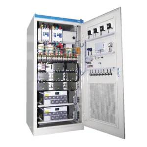
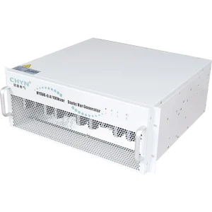
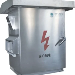
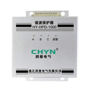
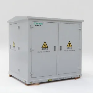
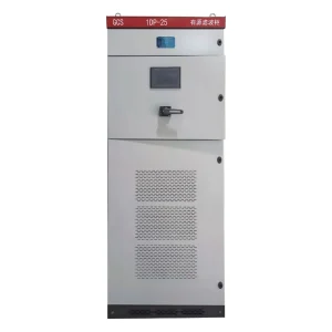
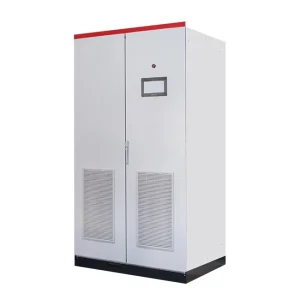
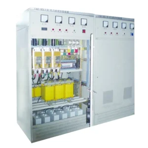
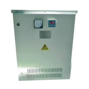
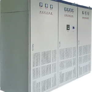
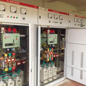
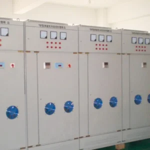
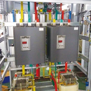
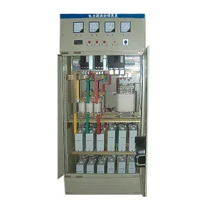
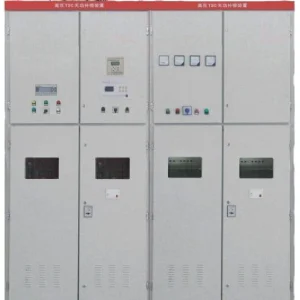
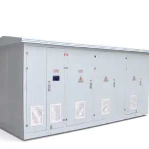
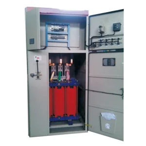
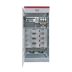
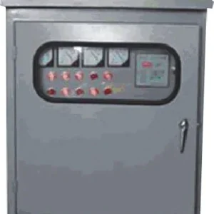
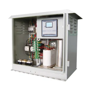
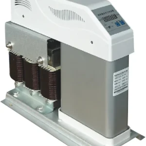
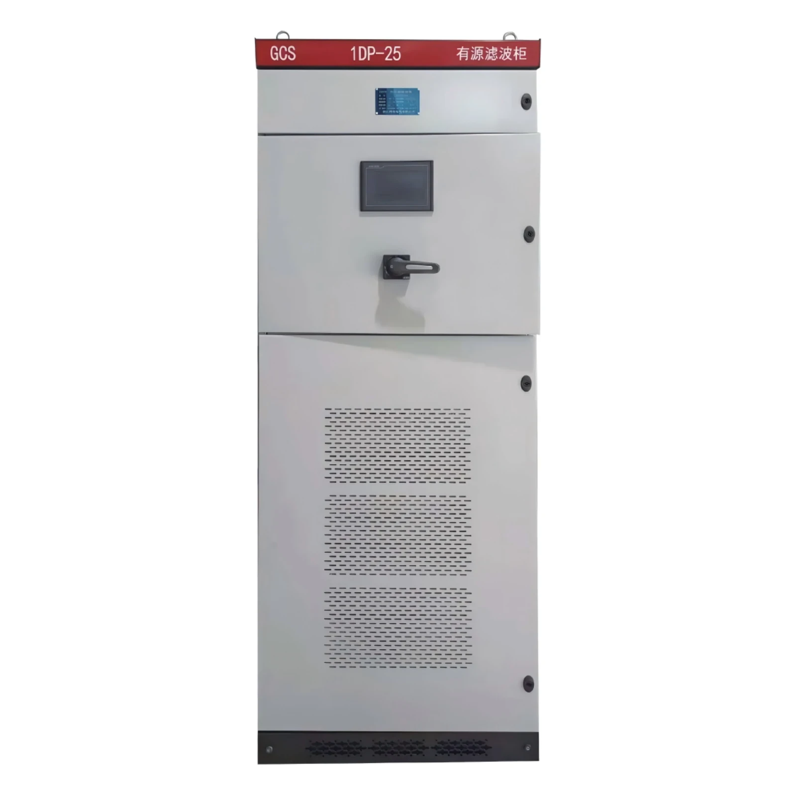
The CHYN HYAPF active power filter belongs to this compensation category. Its product information provides the context for discussing sensing requirements. Confirm the permitted sensor type, interface and settings for the ordered configuration. Do not assume that a general CT recommendation from another filter manufacturer applies to this unit.
The underlying control problem is discussed in research on shunt active filter analysis and control. The public research record explains the current-tracking objective; it does not establish a CHYN sensor specification. For the broader operating principle, see how an active harmonic filter works.
Distinguish core saturation from other errors
A conventional magnetic CT relies on its core operating within a suitable flux range. When that range is exceeded, the secondary waveform can become distorted and cease to represent primary current accurately. The relevant conditions involve the sensor design, primary waveform and secondary circuit. A nominal ratio printed on the label is not a complete description of performance.
Input clipping occurs elsewhere in the chain. A sensor can produce a signal that exceeds the receiving electronics' permitted range, causing the recorded waveform to flatten or lose peaks. That is not the same physical mechanism as CT core saturation. Replacing the core without checking the interface can leave the original problem unresolved.
Phase association, polarity and scaling errors can also make compensation ineffective. A current channel connected to the wrong voltage phase can produce an incorrect control relationship even if the sensor itself is healthy. Inspect the approved configuration and wiring records before treating an unusual spectrum as evidence of magnetic saturation.
Real converter limits form another category. If independent measurements and controller inputs agree but the requested compensation exceeds available output, the problem may be capacity or duty allocation. Use active harmonic filter sizing to examine that separate question. Do not enlarge the filter simply because an unverified controller reading appears high.
Trace the complete sensor and secondary circuit
Collect the sensor model, ratio, rated output, accuracy information and frequency-response documentation. Establish whether the interface uses a conventional current output, a voltage output or another specified arrangement. These interfaces are not interchangeable. Record the exact receiving input and any external conditioning components rather than describing everything as a generic CT.
For a conventional current-output CT, review the complete secondary burden. Include the input impedance, outgoing and return conductors, terminals and test facilities as applicable. Compare the assembled circuit with the sensor manufacturer's requirements. A long cable route can change the burden even when the cabinet and CT model remain unchanged.
Inspect split-core closure, mounting and physical condition where relevant. Contamination at the mating surfaces or a poorly closed core requires attention, but do not diagnose its effect from appearance alone. Record the defect and obtain the appropriate manufacturer disposition. Confirm the conductor arrangement and installation position against the approved drawings.
Never open the secondary of a conventional current-output CT while primary current is flowing. Dangerous voltages can result. Isolation, shorting facilities, testing and reconnection require qualified personnel following the approved procedure. Different sensor technologies require their own instructions; a safety rule for one interface must not become permission to experiment with another.
Use burden arithmetic as a screening check
For a resistive burden example, apparent power is S = I²R, where S is in volt-amperes, I is secondary RMS current in amperes and R is total resistance in ohms. At a secondary current of 5 A and a total resistive burden of 0.4 Ω, the burden is 5² × 0.4 = 10 VA. This is illustrative arithmetic, not a recommended burden for a CHYN sensing circuit.
The calculation identifies a condition to compare with the CT documentation. It does not predict the exact saturation point, harmonic accuracy or response to a transient. Real secondary impedance may include reactive components, and distorted current needs more careful evaluation than a single fundamental-frequency number. Use measured circuit information and the correct sensor data.
OpenEnergyMonitor's original CT test report demonstrates why burden, waveform distortion and phase error deserve separate examination. Its results concern a specific small sensor and measurement setup. They must not be transferred as numerical limits to industrial AHF CTs. The useful lesson is to verify the waveform and interface rather than rely on a nominal RMS reading alone.
Run a controlled comparison before changing settings
Define a representative operating state and document which nonlinear loads are running. Record source voltage, load current and relevant harmonic components using an independent instrument with suitable sensors and bandwidth. Capture the controller's corresponding readings with aligned timing. A comparison taken during changing production may falsely suggest measurement error.
Where the approved commissioning procedure allows it, compare filter-disabled and filter-enabled records under equivalent load conditions. Keep the measuring boundary and instrument configuration fixed. Identify whether a discrepancy exists before compensation starts or appears only when the filter operates. Neither observation alone proves the cause, but it narrows the next investigation.
Evaluate current amplitude and phase information as well as total distortion. A matching RMS value does not guarantee that peaks, harmonic components or phase relationships are correct. Likewise, different THD percentages may reflect different fundamental currents rather than different absolute harmonic current. Retain the underlying values needed to interpret each percentage.
Match symptoms to a verification path
This diagnostic table proposes evidence to collect. It is not a substitute for sensor-specific test criteria, and none of the symptoms should be treated as a confirmed diagnosis without the corresponding checks.
| Observed symptom | Possible explanation | Useful verification |
|---|---|---|
| Error grows at higher current | Core saturation, input limit or operating-range mismatch | Compare independent waveforms and approved sensor/input ranges |
| Only one phase behaves unusually | Phase mapping, connection or individual sensor issue | Check channel association and phase-specific records |
| RMS values agree but spectra differ | Bandwidth, waveform or processing differences | Compare harmonic amperes, settings and synchronized captures |
| Readings change after cable modification | Secondary burden, connection or interference change | Review the complete circuit against its previous documented state |
| Inputs agree but residual harmonics remain high | Capacity limit, compensation priorities or system conditions | Check available output and the approved control objective |
Prepare a sensor enquiry and acceptance record
Provide the supplier with the primary operating-current range, expected waveform, relevant harmonic orders, conductor arrangement and proposed sensor location. Include cable length, conductor details, receiving input information and the intended compensation boundary. State whether the filter shares other compensation duties that can affect available current.
Ask for written confirmation of sensor compatibility, installation requirements and the evidence needed to demonstrate correct sensing. Do not ask only for a preferred ratio. A suitable ratio with inadequate frequency performance or an incompatible input remains an unsuitable measurement arrangement. Record any limitations at low load and during transient events.
When a CT or cable is replaced, preserve the previous settings and record every approved change. Repeat the affected phase, scaling and performance checks before normal compensation resumes. Keep the commissioning record tied to the actual sensor model and wiring revision so a later maintenance team does not repeat a previously rejected combination.
For systems with a neutral conductor, sensor configuration and neutral duty require an additional system check. The article on three-wire versus four-wire active filters covers that boundary. Correct saturation assessment does not by itself establish that a three-wire device can perform a four-wire compensation task.
Educational background: current transformers
The NPTEL lecture below introduces current and potential transformer operation. It helps explain the measurement chain discussed here. Its educational examples do not set the sensor interface, burden or acceptance limits for a particular CHYN filter.

Watch the educational lecture on YouTube.
Frequently asked questions
Does high residual THD prove CT saturation?
No. Check sensor waveforms, scaling, phase association, input range, filter capacity and operating conditions. Several different problems can produce poor compensation.
Can a larger CT ratio always solve saturation?
No. The ratio is only one selection factor. The complete burden, core design, measurement range, waveform and receiving interface must suit the application.
Is a correct RMS reading enough to verify the CT?
No. RMS agreement can coexist with waveform or phase errors. Compare the relevant harmonic components and synchronized measurements using suitable instruments.
Can I disconnect a CT to inspect its signal while the load runs?
Do not open an energized conventional current-output CT secondary. Qualified personnel must use the approved isolation and test arrangement for the specific sensor and installation.