
 Zhejiang Hongyan Electric Co., Ltd.
An active harmonic filter CT ratio must match both the installed current transformer and the controller's scaling convention. Select it from the monitored circuit's operating current range and the filter manufacturer's approved sensor requirements, then verify the result against an independent measurement. Do not choose the ratio from the AHF output-current rating alone. A correctly sized filter can still receive an incorrectly scaled measurement, while a plausible current display does not prove that the complete measurement chain is suitable for harmonic compensation.
This guide addresses ratio selection, parameter entry and verification. For the broader compensation-current calculation, use active harmonic filter sizing. Ratio verification should be completed before an apparent performance shortfall becomes a reason to order another module.
Separate monitored current from filter output current
The external CT observes current at its installed measurement boundary. The AHF injects compensating current through a different branch. Those currents are related through the network and control arrangement, but their nameplate values are not interchangeable. A sensor observing a main feeder must be evaluated for that feeder's duty, even when the connected filter has a much smaller output rating.
Start with a marked single-line diagram showing the CT location, the filter connection and the loads included in the intended compensation zone. Identify alternative supplies and any parallel feeders. Record which operating modes the proposed arrangement covers. This prevents a ratio calculation based on one branch from being reused for an entirely different measurement boundary.
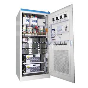
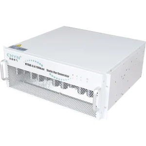
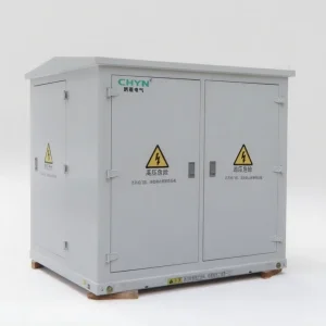
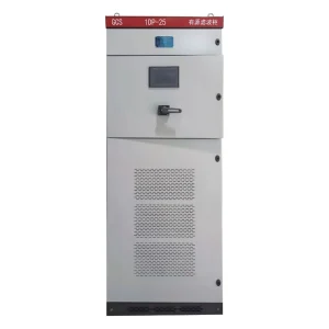
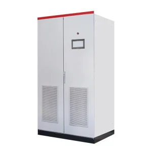
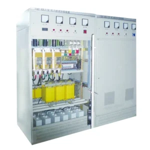
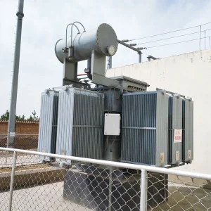
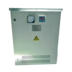
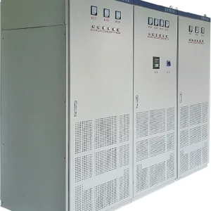
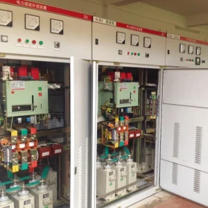
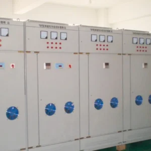
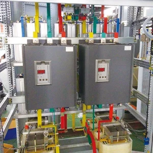
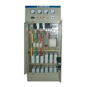
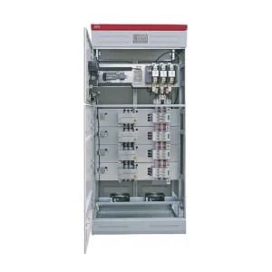
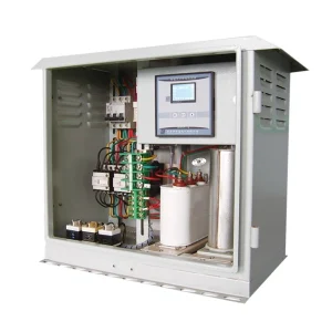
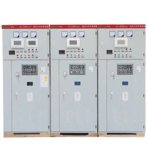
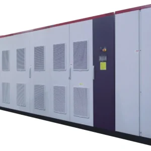
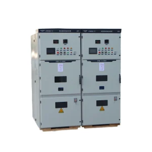
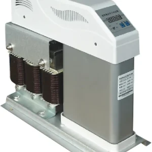
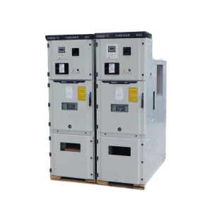
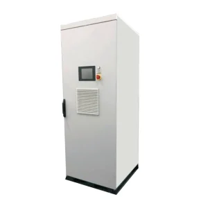
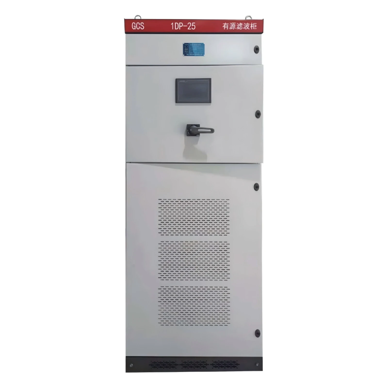
The CHYN HYAPF active power filter is the relevant product family for this discussion. Obtain the approved external-sensor specification for the offered configuration. A general product description does not establish the permissible CT secondary current, ratio range, cable length or frequency-response requirements for every supplied version.
Read the ratio as two current ratings
For an ideal conventional current-output CT, Is = Ip × Isr / Ipr. The subscripts p and s identify primary and secondary current; pr and sr identify their rated values. All four quantities are in amperes. The equation describes scaling within the CT's suitable operating range, rather than predicting accuracy under every load or fault condition.
As a calculation example, an 800/5 A CT carrying 320 A primary current ideally delivers 2 A secondary current: 320 × 5 / 800 = 2. A controller configured for 400/5 A would interpret that same 2 A as 160 A. This is a deliberate illustration of a factor-of-two setup error, not a recommended CT selection or a measured CHYN result.
Parameter labels need careful reading. One interface may request primary and secondary ratings separately, while another requests their numerical quotient. For 800/5 A, the quotient is 160. Entering 800 into a quotient field would therefore create a different error. Use the exact controller instructions and retain a screenshot or parameter export showing the field names as well as the values.
Choose from the operating envelope and supported input
Prepare a current profile that includes normal production, lightly loaded operation, planned additional loads and permitted temporary duty. Use measured records where available and identify estimates clearly. Ask the supplier to review the proposed ratio against this profile. There is no defensible universal multiplier that can be copied from an unrelated filter manual and treated as a CHYN requirement.
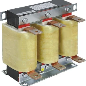
Check the secondary signal type before ordering. A conventional 1 A or 5 A current-output CT is not automatically interchangeable with a voltage-output sensor or a Rogowski coil. Matching the aperture and the primary-current number is insufficient. The sensor interface, insulation suitability, installation arrangement and controller support must all agree.
For multiple-ratio CTs, record the selected terminal pair or tap. Photographing the front label without identifying the connected terminals can leave the effective ratio uncertain. Ask for an approved assembly drawing when access is restricted, and resolve any discrepancy while the equipment is safely isolated under the site's work procedure.
Keep ratio, accuracy and harmonic response separate
Measurement Canada's instrument-transformer specifications describe marked ratio, secondary burden and accuracy under defined conditions. Their scope is revenue metering with solid-core CTs. They provide useful terminology, but they do not certify that a metering CT is suitable for an AHF's harmonic measurement task.
Request the sensor's documented performance over the frequencies and currents relevant to the controller. A fundamental-frequency accuracy class should not be converted into an unsupported claim about every harmonic. Similarly, correcting a scaling parameter does not repair a waveform distorted by a sensor operating outside its intended range. Review AHF CT saturation separately when the waveform itself is suspect.
CR Magnetics' explanation of CT ratio error shows how excitation characteristics and the connected secondary burden affect measurement. The practical implication is to assess the actual connected circuit. A matching ratio label alone cannot establish the performance of an unreviewed combination of sensor, cable and controller input.
Use a selection and verification register
| Item to record | Evidence required | Decision it supports |
|---|---|---|
| Measurement boundary | Marked feeder and filter connection drawing | Whether the current profile represents the intended loads |
| Primary and secondary ratings | Nameplate, selected tap and controller input specification | Whether the sensor and input are compatible |
| Normal and permitted maximum current | Operating records and documented future demand | Whether the proposed range suits the application |
| Burden and cable arrangement | Actual route, conductor details, terminals and connected input | Whether the proposed measurement circuit needs supplier review |
| Controller scaling | Named fields, entered values and configuration export | Whether the software interprets the physical ratio correctly |
| Independent comparison | Same boundary, time, phases and measurement definitions | Whether commissioning observations support acceptance |
This register is an application checklist, not an accuracy-class table or universal acceptance standard. The distinction between ratio and burden follows the references above; the supplier's approved application details establish the actual permissible configuration.
Review the secondary circuit without improvising changes
List the complete connected secondary circuit, including terminal blocks, test facilities and the controller input. Identify any shared instrumentation. Ask whether sharing is explicitly supported before adding another device to a measurement loop. A convenient spare terminal is not evidence that the resulting arrangement has been approved.
CT work requires qualified personnel and the documented isolation and shorting arrangements. Never open-circuit the secondary of an energized conventional current-output CT. Do not disconnect live sensor leads to investigate a display discrepancy. Treat the installed sensor according to its own instructions, especially when a different output technology is used.
Keep the ratio review separate from polarity and phase association. A corrected magnitude can coexist with reversed direction or swapped channels. Record the accepted phase labels and installation orientation together with the scaling values. That record allows later service staff to understand which parts of the measurement chain were actually verified.
Compare like-for-like measurements during commissioning
Agree the comparison method before energization. The independent instrument must observe the same conductor boundary and use a suitable measurement definition. A feeder total-RMS reading should not be compared casually with a display showing only fundamental current or one selected harmonic. Record operating state and timestamps so changes in production are visible.
Where an approved controlled test is available, document expected readings from the physical ratio before observing the controller. For example, the 800/5 A scaling calculation above predicts the display from a known secondary current under ideal interpretation. The test method, permitted injection points and acceptance tolerance must come from the responsible commissioning engineer and equipment instructions.
After scaling is confirmed, evaluate compensation using the agreed performance criteria. Review the AHF current-limiting state if output reaches an operating limit. A ratio check does not establish that the filter has enough output current, and an output limit does not justify changing a correct CT ratio to make the displayed values look better.
Hand over a configuration that can be reproduced
The final package should connect each CT identifier to its physical location, ratio, selected terminals, controller channel and accepted configuration. Include the independent comparison record and any unresolved restrictions. Specify whether planned feeder additions were considered or remain outside the accepted arrangement.
Define review triggers: sensor replacement, controller replacement, restored configuration, altered secondary wiring or a changed supply path. Before reusing old acceptance results, confirm that the documented measurement chain still exists. This simple change record helps prevent a correct commissioning setup from becoming an unexplained scaling error after routine maintenance.
Further learning: instrument transformer principles
The NPTEL lecture below explains current and potential transformers. Use it to understand scaling and measurement concepts; apply the supplied AHF and CT instructions for actual selection, wiring and safe commissioning.

Watch the educational lecture on YouTube.
Frequently asked questions
Should the CT ratio equal the AHF output rating?
No. Evaluate the current at the CT measurement boundary and the supported sensor interface. The monitored feeder current and the filter's compensating output current serve different purposes.
Can I enter only the primary current number?
Only when the controller specifically asks for it. Some interfaces require primary and secondary ratings; others require their quotient. Follow the named fields in the actual instructions.
Does a correct ratio guarantee accurate harmonic sensing?
No. Confirm frequency response, burden, operating range, phase association and installation suitability. Ratio is one part of the complete measurement chain.
What should be saved after verification?
Save the CT identity and selected tap, marked boundary drawing, controller settings, independent comparison results and any restrictions or changes requiring a future review.