
 Zhejiang Hongyan Electric Co., Ltd.

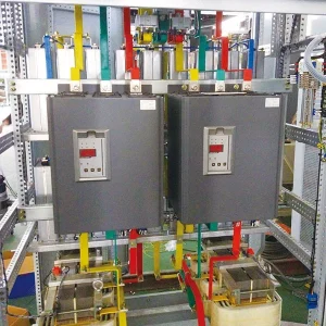
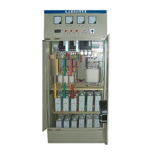
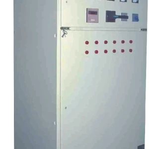
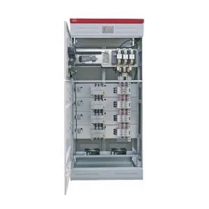


Filter reactor insulation resistance testing evaluates the insulation path included in a specified DC test connection. It does not establish the reactor's inductance, harmonic tuning, turn-to-turn integrity or complete fitness for service. A useful result requires an approved test voltage and duration, a clearly isolated test boundary, recorded environmental conditions and comparison with the equipment's applicable criteria. Qualified personnel must plan and perform the work using the supplied instructions and the site's electrical safety procedure.
This guide helps owners define the test scope, interpret the report and request missing evidence. It is not a universal connection diagram or a substitute for the reactor manufacturer's field-test procedure. For the operating role of the component, begin with why reactors are used with capacitor banks.
Identify which insulation path is being assessed
A filter assembly contains more than a coil. Cables, capacitor branches, protective components, sensors and connected electronics may create additional paths. Before accepting a resistance reading as a reactor result, ask for a drawing marking the components included in the measurement. The report should identify the terminals, reference point and any connections temporarily removed.
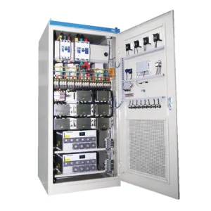
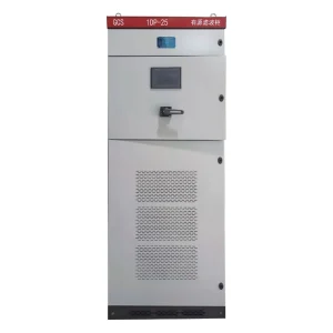
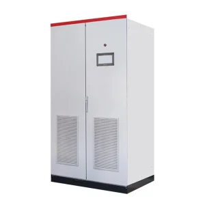
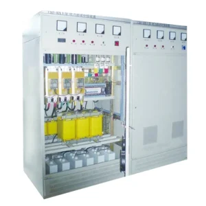
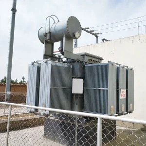
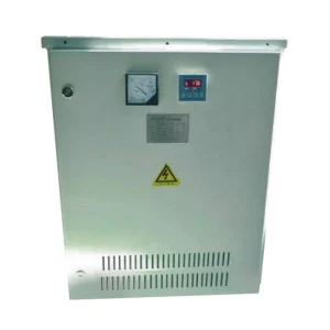
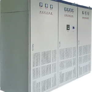
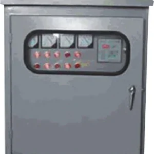
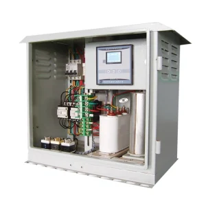
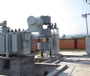
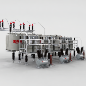
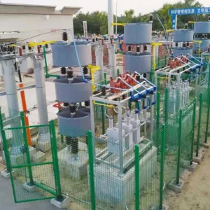
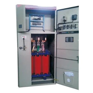
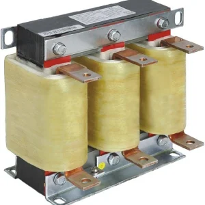
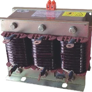
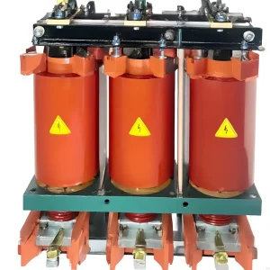
The CHYN filter reactor product family includes dry-type iron-core equipment used with capacitors. Obtain the instructions and test record for the exact supplied model. Product-family descriptions cannot define the test connections or minimum acceptable resistance of every individual assembly.
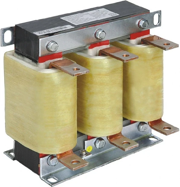
A winding-to-ground assessment is different from a measurement through the winding conductor. Where coils have an electrical connection between them, terminal labels alone do not establish separate insulation paths. Ask the responsible engineer to confirm what the proposed arrangement can measure. Documenting this boundary prevents a later comparison between readings taken across different circuits.
Distinguish insulation resistance from other reactor tests
A high resistance reading to ground does not prove that the reactor has its correct inductance. Conversely, the correct inductance does not establish adequate insulation condition. The two questions require different evidence. The companion guide to reactor inductance testing addresses the electrical value relevant to branch tuning.
Insulation resistance is also different from an applied-voltage withstand test, impulse test, partial-discharge assessment or winding-resistance measurement. Do not relabel one as another in the acceptance report. If the contract calls for several tests, create separate entries with their own method, conditions and results rather than using one satisfactory number to close all requirements.
For suspected turn-to-turn damage, ask the manufacturer which diagnostic methods are appropriate. A winding-to-ground DC result can leave an internal issue unresolved. Procurement and maintenance teams should require a written scope statement describing both the question answered and the questions left open by the selected test.
Approve the voltage and duration before testing
Do not select an insulation tester setting merely because the instrument can produce it. The reactor, its insulation system, its condition and the connected circuit determine which procedure is appropriate. Request the manufacturer's approved field-test voltage, duration, connection method and acceptance criteria before mobilizing the test team.
A factory dielectric test value should not be copied directly into a routine maintenance procedure. Likewise, values quoted for a transmission shunt reactor, a motor or an unrelated low-voltage filter are not automatically applicable to the supplied reactor. Where instructions conflict, resolve the discrepancy with the responsible engineer before applying a test voltage.
Record instrument identity, calibration status and the intended measurement range. If the procedure changes on site, retain the original and revised instructions with the reason and approval. This gives the reviewer a way to distinguish an authorized adjustment from an undocumented attempt to obtain a more favorable reading.
Use a report that preserves comparison conditions
| Report field | Why it matters | Question before accepting the result |
|---|---|---|
| Equipment and connection boundary | Defines the insulation path actually measured | Were cables and other connected components included? |
| Applied DC voltage and elapsed time | Makes the measurement method reproducible | Do these match the approved field procedure? |
| Temperature and environmental observations | Supports comparison with prior records | Were the conditions comparable or properly assessed? |
| Instrument range and result notation | Distinguishes a measured value from a display limit | Does an over-range indication mean only a lower bound? |
| Acceptance reference | Connects the observation with a decision | Which supplied criterion authorizes service? |
| Discharge and restoration record | Closes the temporary test configuration | Who verified safe release and restored connections? |
This is a documentation checklist without universal numerical limits. Megger's diagnostic insulation-testing guide explains that test interpretation depends on the method and conditions. Use its general background alongside the reactor-specific procedure, rather than transferring example limits from another equipment type.
Manage the complete isolated test boundary
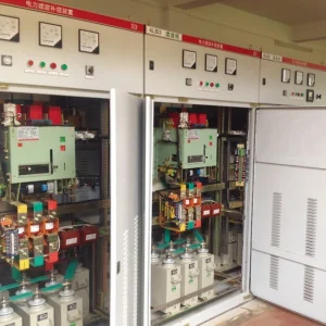
The authorized work plan should identify all possible energy sources, stored energy and backfeed paths. In a capacitor-filter installation, isolation of the supply alone is not a complete statement of the work required. Capacitors and any other energy-storage components require their specified discharge and verification process before access or test connections.
List every item that must be disconnected, protected or included. Electronic monitoring devices and auxiliary circuits need explicit treatment in the approved procedure. Do not assume that a low operating voltage at an auxiliary terminal means it can tolerate the proposed insulation-test voltage. Missing circuit documentation is a reason to resolve the boundary, rather than experiment with the connected assembly.
Keep temporary leads and removed connections under a numbered restoration register. Record where each connection belongs and who will verify it after the test. If several teams are working on the same cabinet, assign responsibility for the final configuration so that one team's completed measurement does not conceal another team's unfinished isolation.
Compare trends without inventing correction factors
When reviewing an apparent deterioration, first compare test voltage, elapsed time, connection boundary and equipment temperature. Record visible moisture, contamination and recent shutdown conditions. A new reading taken under a different procedure should be identified as a new baseline or assessed by the responsible engineer, rather than plotted as an unexplained continuation of the old series.
Use only a correction method applicable to the actual insulation system when temperature normalization is required. A rule of thumb from an unrelated machine should not become a reactor acceptance formula. Keep both the original reading and any corrected value, together with the reference and input temperature used.
An instrument showing a value above its range has supplied a bound, not an exact resistance. Preserve the display notation in the report. For example, an over-range indication cannot justify calculating a precise percentage improvement against a previous finite value. Such arithmetic gives a false impression of measurement resolution.
Investigate a low or inconsistent result systematically
If a reading does not meet the applicable criteria, hold the equipment from return to service pending assessment. Check that the recorded boundary and procedure were correct. Ask whether a lead, terminal contamination or an unintended connected component could have affected the result, and document the evidence rather than assuming the coil has failed.
Cleaning, drying or other treatment must follow the manufacturer's instructions. Retain before-and-after conditions and readings. A higher result following intervention is useful evidence, but the responsible engineer must still decide whether it satisfies the approved criteria and whether the original cause has been controlled.
Do not repeatedly increase the test voltage to force a clearer diagnosis. Nor should an unexpectedly low value be hidden by switching to a different time or connection without explanation. A repeat test should have a defined purpose, an approved method and a record linking it to the original observation.
Discharge, restore and release with separate checks
The Megger S1-series user guide warns against disconnecting test leads before its discharge indications confirm the required state. Follow the tester instructions and the site's verified discharge procedure. Completion of the measurement does not itself establish that the test object can be touched safely.
After the authorized discharge process, check the restoration register, protective connections, temporary leads and final wiring against the approved drawing. The release should identify the person responsible and any remaining restriction. Acceptance of a resistance result and authorization to energize are related but separate decisions.
For a replacement or repaired unit, coordinate the insulation record with the reactor replacement assessment. The final package should identify the installed component, accepted electrical values, insulation evidence and branch configuration. This keeps a satisfactory insulation check from being misused as approval for a component with the wrong tuning or duty.
Further learning: the passive filter circuit
The following NPTEL lecture explains passive power filters. It helps show why coil inductance and capacitor selection determine circuit behavior, while insulation resistance answers a different condition question. The lecture is background on the circuit, not a demonstration of field insulation testing.

Watch the educational lecture on YouTube.
Frequently asked questions
Does a high insulation resistance prove correct tuning?
No. Tuning depends on the branch's electrical components and operating conditions. Verify inductance, capacitance and the approved circuit separately.
Is there one test voltage for every filter reactor?
No. Use the supplied reactor's approved field procedure. Do not transfer settings from a different reactor type or from an unrelated factory test.
Can readings from different temperatures be compared directly?
First assess the test conditions and applicable insulation-specific correction method. Retain original measurements and document any normalization instead of applying an unsupported rule.
Does a passing reading authorize energization?
Not by itself. Complete the required assessment, discharge, restoration and authorized release checks, including any other tests specified for the equipment.