
 Zhejiang Hongyan Electric Co., Ltd.





































An active harmonic filter design starts from the harmonic current the plant actually draws, then sets compensating current, sensing, and site limits around that measurement.
The cabinet is a shunt unit. It watches the current you point it at and injects the opposite of the distortion. Transformer kVA is a background fact, not the ampere rating.
What follows is the rating, the sensors that make that rating true, and the site notes a tender has to carry. The family page for these cabinets is the Active Power Filter Series.
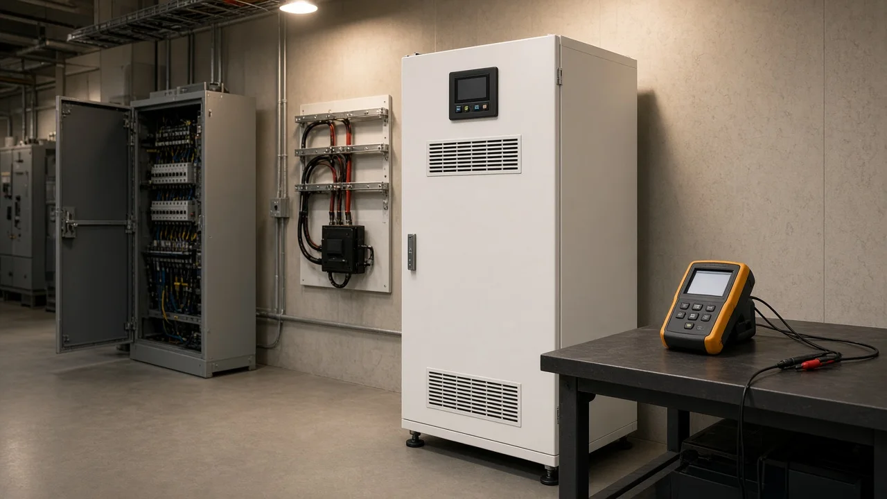
What the design has to decide
The design locks three things: how much compensating current the cabinet must inject, which current the sensors see, and which site limits that current has to respect.
A harmonic is an extra sine wave whose frequency is an integer multiple of the fundamental. Nonlinear load — rectifiers, drives, charging electronics — draws that extra current even when the voltage looks tidy. Those currents sit on a fundamental that is usually 50 Hz or 60 Hz.
If the only question is how active harmonic filter works, the mechanism is short. Sensors read the current, and an inverter injects a cancelling current of the same size and the opposite phase.
Active power filter design also covers reactive current and imbalance. This page stays on the harmonic job and the numbers that size it.
Total harmonic distortion is a ratio of leftover harmonic RMS to fundamental RMS. It tells you how bent the wave is. It is not the ampere rating of the filter.
Rate compensating current from the measured cycle
The rating is the highest harmonic current on a real operating cycle, plus room for any other current the same cabinet will inject.
Start with a log. Skip the nameplate. Capture startup, the production peak, a light period, and the stop.
A single snapshot at lunch misses the ramp. On a steel-plant thread, an engineer told someone who wanted a formula from the furnace nameplate that the current cannot be predicted without the device and the power system around it.
From the field: Missing that log is how filters get oversized or too slow, and then disturb the system they were meant to clean. Physics Forums
Use the harmonic amperes, not the total RMS of the feeder. Total load current includes the useful 50 or 60 hertz work.
The filter supplies the distortion the load wants from somewhere closer than the transformer. It does not stand in for the fundamental work.
If you also turn on reactive-current or imbalance help, that current comes from the same rating. A unit that looks generous for harmonics can sit on its limit once power-factor current is added. Write the priority in the spec: harmonics first, or a stated share for reactive current.
| What you need on the spec | Where the number comes from | What to leave off the rating |
|---|---|---|
| Peak harmonic current on the logged cycle | Power-quality log at the point you intend to clean | Transformer kVA percentage used as the cabinet size |
| Extra current for reactive or imbalance jobs you will enable | The same cycle, with those functions counted | A catalog THD target used as if it were amperes |
| Headroom for a known new drive or charger | The upcoming load, stated as harmonic current | A one-hour snapshot from a quiet shift |
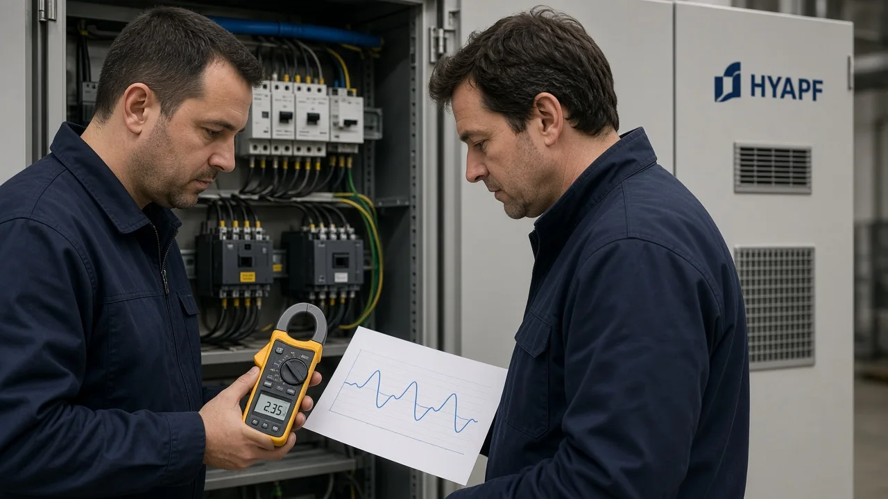
Place the sensing CTs on the current you intend to cancel
The current transformer has to sit on the current the filter is asked to cancel, on the supply side of those loads, with the filter’s own output outside that measurement.
Put the CT too far upstream and the unit tries to clean feeders you never budgeted. Put it on a downstream pocket and the main bus keeps sending distortion toward the transformer.
A protection or metering CT already on the filter feeder is the wrong sensor. That current is the cabinet’s output, not the load it is correcting. Sites have cooked CTs that were never meant for that harmonic duty.
Polarity and phase order belong in the same note as the location. A reversed sensor makes the inverter add to the distortion instead of cancelling it.
Commissioning finds this quickly if someone compares source current with the filter on and off. It is expensive if the first clue is a hotter transformer.
Wire count changes the sensor count. In a balanced three-wire system, triplen currents do not form a neutral return. In a four-wire system they can, and they add in the neutral.
Single-phase electronic loads make that neutral path real. Specify whether the design is three-wire only or must see line-to-neutral current. Write the third sensor into the spec before anyone is standing at the panel.
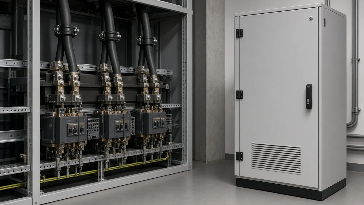
Match response and priority to the load cycle
Response has to follow the steps you actually logged, and every extra job you enable spends the same compensating current.
A welder, a crane, or a drive that ramps in seconds will not be covered by a rating taken from a flat average. Slow correction, or a unit already at its current ceiling, leaves distortion in the source.
Write the fastest load step you care about next to the rating, in ordinary language. “Holds through the press cycle” is enough. Skip brochure microseconds.
When the cabinet reaches the current it can inject, the rest of the harmonic current stays on the supply. That leftover is a sizing outcome.
If the log shows peaks above the chosen rating, say so in the spec and either raise the current or parallel another module. Parallel units are how shunt designs add current. They still need the measurement first.
Leave reactive current and imbalance as explicit switches. Enabling them on day one, with no ampere share written down, is how a harmonic design quietly becomes too small.
Use a shunt design, and keep passive filters in their lane
A shunt active power filter is the right shape when the harmonic set moves with the load. A passive filter is the simpler shape when one order dominates and stays put.
The shunt unit connects in parallel and injects compensating current. It can follow a spectrum that changes when drives start and stop.
A passive branch is inductors and capacitors tuned to a frequency. That is a good fit for a stable order. It struggles when the plant’s mix of drives, chargers, and IT loads keeps shifting, and it can resonate with the source impedance.
Existing detuned capacitor banks stay in the site notes even when you choose the active path. They already shift current at certain frequencies.
The filter spec should say they are present, where they connect, and whether anyone may switch them while the active unit runs. Keep that coordination in the site note.
If the whole decision is “active or passive for this plant,” treat that as a separate comparison. Here the test is narrower: does the spectrum hold still, or does the rating have to track a moving load?
Write the site conditions into the specification
Voltage, wire count, the point you care about, existing capacitors, and physical room decide whether the current you calculated can actually be installed.
Match the cabinet voltage to the bus. Nonlinear loads also heat capacitors, motors, transformers, and cables, which is why the log belongs at the point whose equipment you are trying to protect.
People often discuss a limit at the point of common coupling, where another customer could also be supplied. A filter on one MCC does not automatically clean a different feeder or the utility interface. Write the point in the spec.
IEEE 519 is a commonly cited recommended practice for that conversation. Naming it does not list the cabinet, and it does not replace the measured current.
The specifier still has to say which point and which limit were agreed. Years in business and systems delivered stay off this spec.
Heat and spare bays matter once modules are paralleled. A modular shunt design can grow with a stated future harmonic current. It cannot grow if the room, the bus, or the CT ratio was chosen only for today’s snapshot.
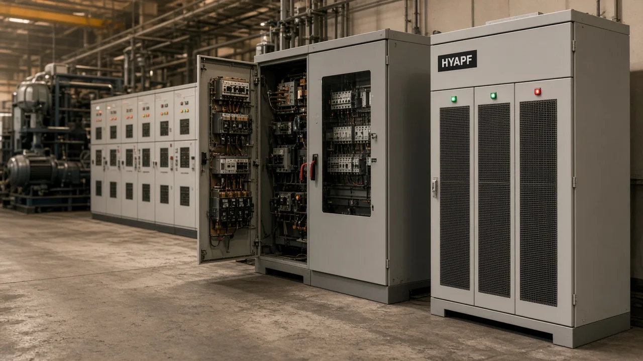
Where HYAPF fits this specification
HYAPF fits when the spec you just wrote is a low-voltage harmonic-injection job, and the published voltage, order range, and response line cover that job.
The HYAPF Series Active Power Filter measures load current in real time and injects an equal, opposite harmonic current into low-voltage distribution networks. The page says the modular architecture can be sized for the required filtering current, can address multiple orders, and can support reactive-power or load-imbalance compensation. That last pair is the shared ampere budget from the rating section — enable it only if the measured cycle still fits.
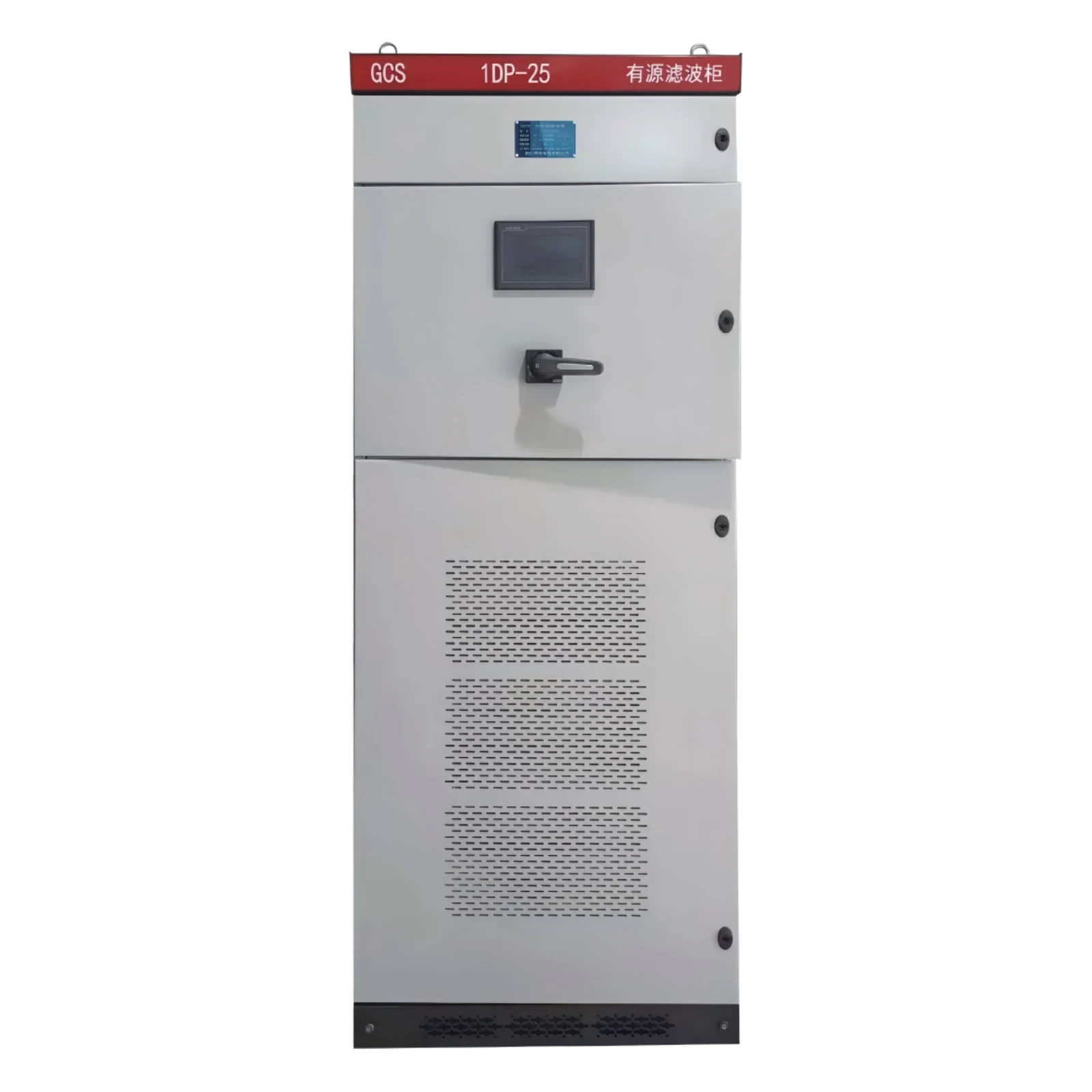
Use the published lines as product statements, not as a site test result.
The published voltage line is 400 V / 690 V, optional.
The same table lists a response time less than 10 ms.
Stated control accuracy on that page is THD below 5%.
Order coverage printed there runs from the 2nd through the 51st. Topology is stated as a modular three-level design, with switching frequency up to 20–30 kHz, and modules that can run in parallel.
Outside those voltage lines, or when the logged current needs a high-voltage compensator, this is the wrong cabinet. A tuned passive bank is the wrong recommendation when the spectrum moves. A high-voltage static var generator on the same hub is a different product.
| Published HYAPF line | What the specifier can copy | What it does not prove |
|---|---|---|
| 400 V / 690 V, optional | Bus match for a low-voltage spec | A listing to a utility or building code |
| 2nd–51st order | The order range printed on the product page | That every site will need the full range |
| Response less than 10 ms | The stated response line | That a slower load step was measured on your bus |
| THD below 5% | Stated control accuracy on the product page | A measured result at your point of common coupling |
| Parallel, hot-swappable modules | A way to add filtering current later | Today’s rating if you never logged the peak |
FAQ
How do I start an active harmonic filter design if I only have transformer kVA?
Treat kVA as the supply context and go get a current log. The cabinet rating is harmonic amperes on the cycle you care about. A percentage of transformer kVA skips diversity, spectrum, and the peak at startup.
Does the compensating-current rating equal the total load current?
No. Total load current includes the fundamental work. Compensating current is the harmonic part, plus any reactive or imbalance current you ask the same cabinet to inject.
Where should the sensing CT sit relative to the filter and the nonlinear loads?
On the supply side of the loads you intend to clean, so the filter output is outside the measurement. A CT on the filter feeder sees the cabinet, not the load.
What changes if the system has a neutral and single-phase electronic loads?
Triplen current can return on the neutral. The spec has to say the system is four-wire and that the sensors must see that path. A three-wire sensing note will miss it.
How fast does the response need to be relative to the load cycle?
Fast enough for the steps on the log — the press, the ramp, the charger inrush — not a microsecond copied from another maker. If the cabinet is already at its current limit, extra speed does not cancel the leftover.
When is a detuned passive filter still the simpler design?
When one harmonic order dominates and the load mix does not wander. Once drives, chargers, and IT loads keep changing the spectrum, a shunt unit that tracks the current is the closer fit.
Can I claim IEEE 519 or UL compliance because a filter is installed?
IEEE 519 is a practice you apply at an agreed point, using the measured current. A cabinet on a product page is not a UL listing.
It is also not a grid-code certificate. Those claims need their own evidence.
References
- Harmonics (electrical power) — integer-multiple harmonics, typical power-system fundamentals, and triplen current on a four-wire neutral.
- Active power filter — shunt injection of an equal, opposite current, and how that differs from a tuned passive branch.
- Microgrids and Power Quality — nonlinear loads, extra heating, and IEEE 519 named as a practice rather than a product listing.
- Circuit diagram of an active power filter — field objection that nameplate data cannot replace a power-system measurement.