
 Zhejiang Hongyan Electric Co., Ltd.





































A shunt capacitor bank supplies leading reactive power in parallel with an inductive plant bus, and protection has to take a failed unit or element out before the remaining units sit on a lasting overvoltage. Shunt capacitor bank fundamentals and protection is that pair of jobs: the stack of the bank, the fuse style, and the unbalance and switching checks that follow.
The next sections stay with an industrial bus. They cover how series groups share voltage, how three fuse styles fail, when unbalance should alarm or trip, what a switching operation can do to that relay, and where one cabinet fits.
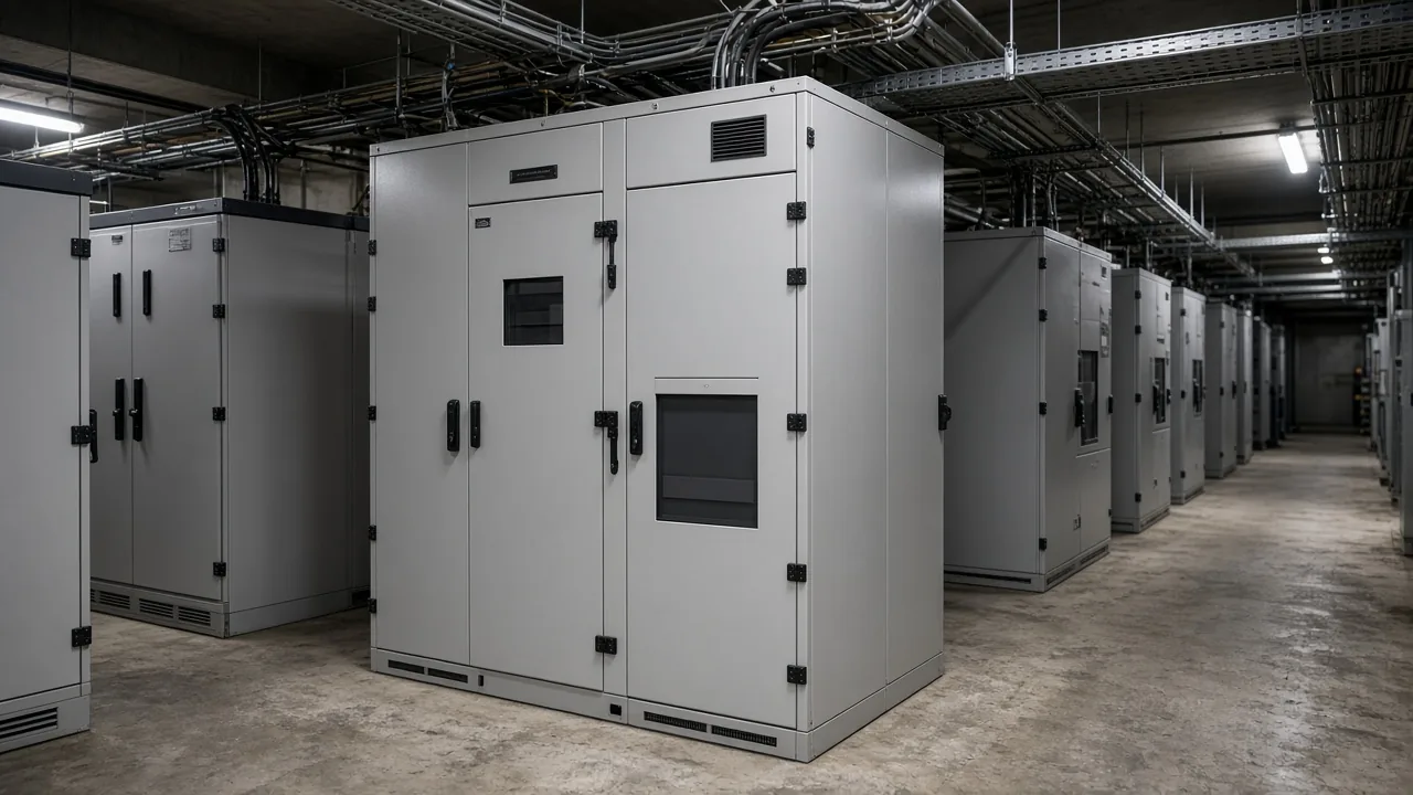
What a shunt bank supplies when voltage sags
It still supplies leading reactive power, but that output falls with the square of bus voltage. Motors and transformers draw lagging current. A parallel capacitor supplies the leading share locally, so less of that current has to travel in from the source.
Reactive output of a shunt bank falls with the square of bus voltage, so the bank produces less kvar when the plant bus is already low. A nameplate kvar value is the output at rated voltage. On a sagging bus the same capacitor unit delivers a smaller share, which is why voltage support and reactive supply are one problem rather than two brochures.
People sometimes hear "shunt" as a meter resistor. On this equipment it means the capacitor unit is across the phases, in parallel with the load. A series capacitor is a different device, inserted in the line, and it is outside this protection story.
A buyer who only wants a list of benefits can stop at the parallel idea. The protection problem starts the moment one element inside a capacitor unit fails and the voltage on its neighbors changes.
How series groups and the wye connection set unit voltage
Series groups split the phase voltage, and a grounded or ungrounded wye decides which current the relay can see. A capacitor unit is a set of smaller elements in series and parallel inside one case.
Several units in parallel form a group. Groups in series then stand from the phase conductor toward the neutral.
Capacitor bank design starts with that stack. More series groups mean less voltage on each group, and fewer parallel units mean a larger voltage step when one unit is removed.
The relay does not see a failed can as a vague label. It sees the current or voltage that this particular stack produces after the failure.
A grounded wye ties the neutral to earth. That path can swallow a lightning surge and it also gives harmonic current a route into ground. Those same ground currents show up in ground relays and in the neutral of nearby equipment, so the bank and the feeder protection have to be read together.
Leave the neutral off earth and the bank can float. A double-wye bank uses two such sections and compares them.
System unbalance that hits both sections together tends to cancel in the link between the neutrals. A failed capacitor unit in only one section does not cancel, which is why that link is a useful place to watch.
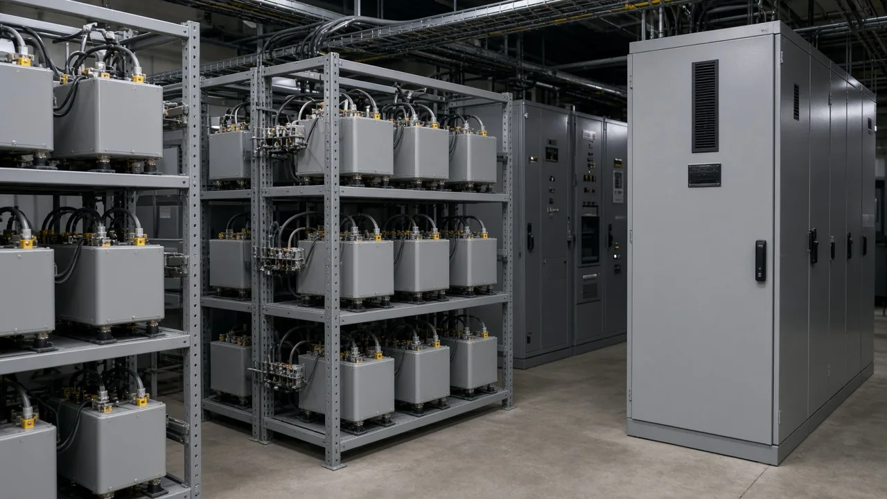
How external fuses, internal fuses, and fuseless strings fail
An external fuse removes a unit, an internal fuse removes an element, and a fuseless string leaves a shorted element in the chain. The relay setting follows that choice. Treating every bank as "a fuse on the bushing" hides the cases where the fuse is inside the can, or where there is no fuse at all.
| Arrangement | What the failure does | What unbalance protection is watching |
|---|---|---|
| External fuse | Removes one capacitor unit from its parallel group | Higher voltage on the units that remain in that group |
| Internal fuse | Removes one element inside the capacitor unit | Higher voltage on the parallel elements left in service |
| Fuseless bank | Leaves a shorted element in the series string | Higher voltage on the healthy elements that remain in series |
An external fuse is the visible one between the capacitor unit and the bus. When an element welds, parallel units dump current through that fuse.
After it opens, the failed unit is gone and the survivors in the group run at a higher voltage. A second failure in the same group pushes that voltage again.
An internal fuse is a small link around one element. It clears that element and leaves the rest of the capacitor unit in service, again at a somewhat higher voltage.
The can stays on the rack. A walkdown that only looks for a blown external fuse will miss it.
A fuseless bank has no fuse to coordinate with. The element fails shorted, the string stays energized, and the voltage that element used to hold moves onto the remaining elements.
Fuseless strings are described as uncommon below about 34.5 kV, because one shorted element then takes a large share of the voltage. Above that range, a long series string can lose one element and stay within a small step.
Below that range, designers more often keep a fuse or accept a trip on the first short.
There is also an unfused series-parallel arrangement used where a long fuseless string is impractical. It still has no individual fuse. The point for the reader is the same: the protection must notice a short, not an open fuse.
How unbalance protection chooses alarm or trip
Alarm when the first failure is visible, and trip before the remaining units stay on the continuous overvoltage that capacitor practice treats as the limit. A healthy bank is nearly symmetrical.
A balanced double-wye link carries almost no current. One failed capacitor moves that current or shifts the neutral voltage. That shift is the signal.
A course account of shunt-capacitor standards describes continuous service up to 110% of rated terminal RMS voltage. That account also describes withstand of 135% of nominal current.
The same course describes a unit discharge element that brings residual voltage to 50 V or less in 5 minutes.
The practical split used in protection writing is an alarm near the first opened fuse or shorted element, then a trip if more failures would hold the survivors above that continuous voltage level. A handbook treats that continuous-voltage limit as the level the delayed trip is trying to respect, and it says the alarm should sit above the bank's natural unbalance so a healthy bank does not chatter.
A practitioner thread on a 13.8 kV double-wye bank records that matching open fuses on both legs of one phase leave neutral current at zero. The neutral CT scheme is blind to that pair.
A neutral voltage scheme can see it, because the neutral still moves. The same thread records that this voltage element also tripped when other feeders on that bus faulted.
The floating neutral shifted with the system, and the bank relay interpreted a remote fault as its own.
A reply on that same bank alarms the first open fuse, and delays the neutral element long enough for the feeder relay to clear.
From the field: On a 138 kV shunt bank, an imbalance lockout left one parallel group of fuses open while the other groups on that phase stayed intact, and the cans still measured near nameplate. Source: Physics Forums substation capacitor bank thread.
Finding which can failed is a separate job. Unbalance protection tells you the bank is no longer symmetric.
On a fuseless bank it does not, by itself, point to the rack position of the bad unit.
In a separate thread, the example unbalance current rises from almost 0 A to about 1 A, and a 200:5 CT is treated as a poor way to see that 1 A. A metering-class core sized near the unbalance current is what those engineers argue for.
A protection core built to stay accurate through a large fault can be too coarse for the small steady change in that example. The ratio has to be chosen for the bank in front of you.
The neutral CT also has to be insulated for system voltage. A fault that takes the whole neutral up to line potential puts that voltage on the CT. Line overcurrent, not the sensitive unbalance element, is what should see a destroyed bank.
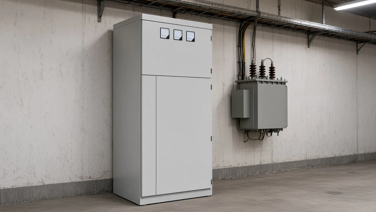
What switching does to inrush and to a voltage differential
Inrush and trapped charge are switching events, and a bypass opening can also saturate the tap transformer used for voltage differential. Closing the first bank on a bus draws energizing current from the source. Back-to-back switching is the sharper case: a second bank closes while the first is already on, and the inrush circulates between them at a higher frequency.
Back to back capacitor bank switching is one reason a series reactor, or a pre-insertion contact, shows up on the single line. The reactor is there to limit that transient, and on some banks a larger percent also shifts a harmonic.
That choice belongs in the harmonic study. The unbalance relay still has its own job.
Capacitor bank switching transients in power systems also include outrush into a nearby fault, voltage magnification on a lower-voltage bank, and reclosing while the capacitors still hold trapped charge. With no discharge path, that trapped voltage adds to the source at the next close. Discharge resistors or a voltage transformer used as a discharge path exist so the next close does not start from a full residual.
A different misoperation shows up on two-stage banks that use voltage differential. Opening the bypass can leave a direct-voltage offset across the capacitors.
The offset saturates the tap voltage transformer, the relay measures a smaller fundamental, and the differential asserts even though no element failed. One utility had to block that differential during the switch until the offset decayed.
The lesson for a plant with a tapped bank is to ask how the scheme behaves during the bypass, not only during a welded element.
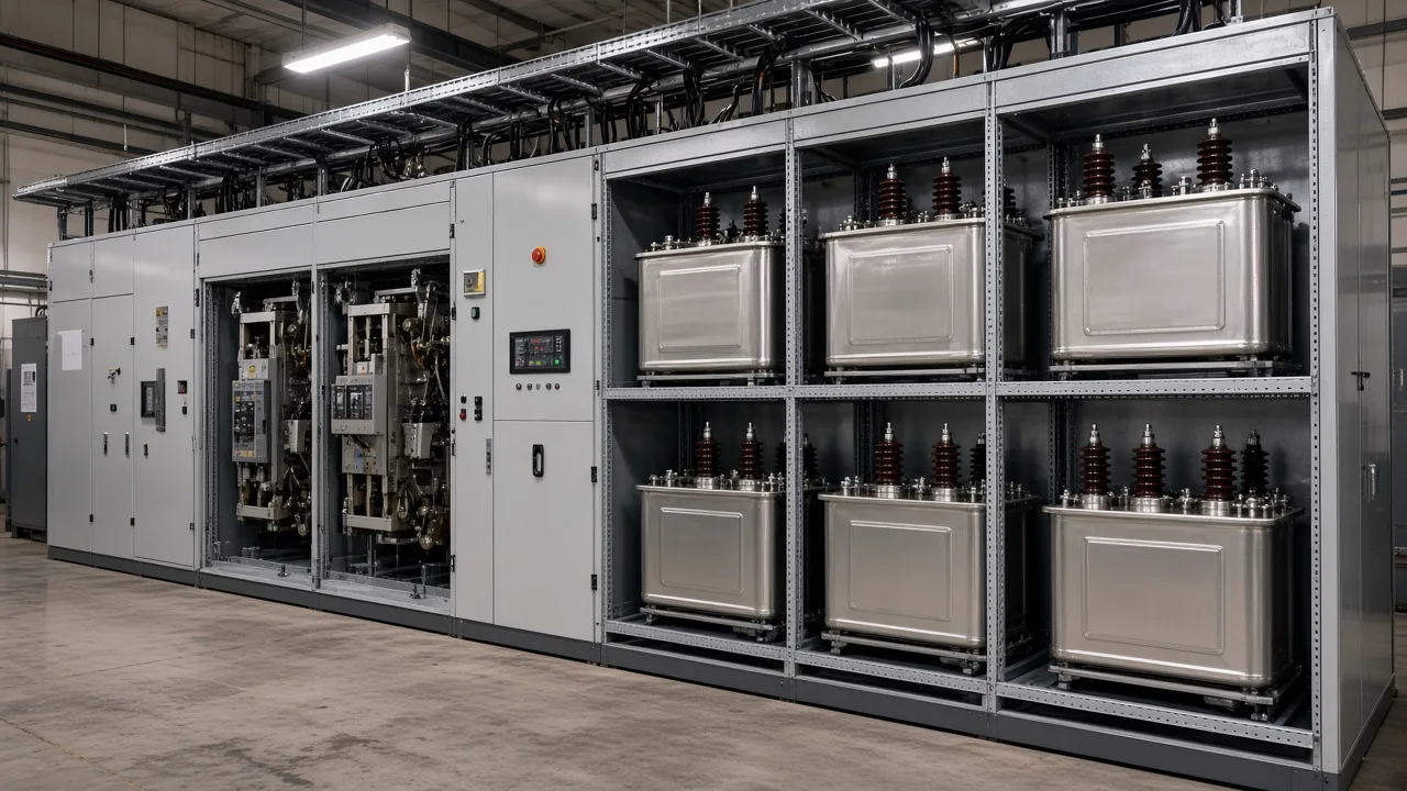
How overcurrent sits beside unbalance
Phase overcurrent is the backup for a short the neutral unbalance element is not meant to carry alone. Unbalance is sensitive on purpose.
It is set for a small asymmetry. A fault between phases, or from a bus to the frame, is a large current and belongs on the phase and ground overcurrent elements.
A protection handbook discusses a delayed phase-overcurrent start near 135% of nominal current for an earthed wye bank and near 125% for an unearthed bank. The idea is a start high enough to ignore normal load and low enough to see a fault inside the bank that the instantaneous element might be set above. A high-set step, where it is used, is discussed high enough that back-to-back inrush does not operate it.
The job split is unbalance for the damaged element, overcurrent for the hard fault, and a time order that lets an external fuse or a feeder relay finish before the bank breaker opens.
Undervoltage has a smaller role. It keeps the bank from being reclosed, or left closed, when the bus is not actually there. It does not detect a single failed can.
Where the HYTBB cabinet fits this shunt duty
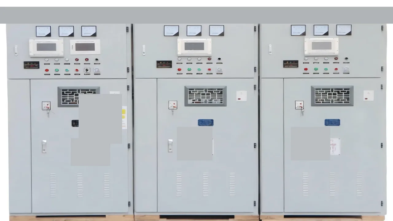
The HYTBB cabinet is the shunt match for this duty. The HYTBB cabinet is a 50 Hz shunt capacitor bank for inductive reactive power, with an isolated or non-effective neutral, for a bus in its 10(6)–35 kV span. The HYTBB medium and high voltage reactive power compensation cabinet is that shunt capacitor bank.
The HYTBB cabinet is rated 50 Hz and 10(6)–35 kV. The capacity span runs from 50 to 20,000 kvar. The neutral is isolated or non-effectively grounded.
A specification that calls for a solidly grounded wye rack is looking at a different arrangement from this cabinet.
| Rating | HYTBB cabinet |
|---|---|
| Rated voltage | 10(6)–35 kV |
| Rated frequency | 50 Hz |
| Rated capacity | 50–20,000 kvar |
| Neutral connection | Isolated neutral or non-effective grounding |
| Named protection | Overcurrent, overvoltage, unbalanced load, and short-circuit |
Look for high-voltage parallel capacitors, a series reactor, vacuum circuit breakers, current transformers, discharge resistors, and a control and protection unit. Switching can be fixed, or manual or automatic in groups.
The cabinet can sit with KYN28 or KYN61 switchgear. Series reactors on that cabinet are 4.5–6% for 6 kV systems and 12–13% for 10 kV systems.
The HYTBB cabinet is for long-term operation at 1.0 times rated voltage, with a short-duration withstand up to 1.3 times rated voltage.
The cabinet states residual voltage below 50 V within three minutes in one place and within five minutes in another.
A buyer should treat the discharge time as something to confirm on the order, because the two lines do not agree. The general capacitor-unit course cited earlier describes the unit discharge element on its own terms.
The HYTBB cabinet is a fit when the bus matches its 50 Hz rating, the voltage sits in the 10(6)–35 kV span, and the neutral practice matches an isolated or non-effectively grounded bank. This cabinet is the wrong fit when the project is a pole-mounted line device or a specification written only around a grounded-wye utility rack. The category that holds this cabinet and the related high-voltage compensation equipment is the high-voltage power factor compensation series.
Readers who want the transient catalog after this protection overview can continue with capacitor bank switching transients in power systems and with back to back capacitor bank switching.
FAQ
What is the purpose of a shunt capacitor?
It supplies leading reactive power in parallel with an inductive load so the source does not have to deliver all of that lagging current. On a plant bus the practical result is a better power factor and a bus that sags less for the same load, within the limit that output still falls when voltage falls.
What are the two types of capacitor banks?
The split that matters here is shunt versus series. A shunt bank is in parallel with the bus and is the subject of this protection discussion. A series bank is inserted in the line and is a different application.
Why can neutral current stay near zero when a capacitor has already failed?
On a double-wye bank, identical open fuses on both legs of the same phase can balance each other. The link between the neutrals then carries no extra current, even though two units are out. A neutral voltage measurement can still move in that case.
Why does a neutral overvoltage relay trip during a feeder fault outside the bank?
An ungrounded neutral floats. A fault on another feeder at the same voltage shifts that neutral, and a sensitive voltage element can read the shift as a capacitor failure. A short delay lets the feeder protection clear before the bank breaker opens.
Why do protection engineers reach for a metering CT on unbalance current?
The current they are trying to see is a small steady change, not a fault of many times rated current. A CT whose ratio is huge compared with that change produces almost no secondary current. A core and ratio chosen near the expected unbalance are easier to set.
What happens to shunt reactive output when bus voltage drops?
Output follows the square of the voltage. A bank that is fully useful at rated voltage delivers a clearly smaller kvar when the bus is low, which is exactly when voltage support would be welcome.
Why can a bypass-switch opening upset voltage-differential protection?
Opening the bypass on a two-stage bank can leave a direct-voltage offset on the capacitors. That offset saturates the tap voltage transformer, the measured fundamental shrinks, and the differential can assert with no failed element. The scheme has to be checked for that switching state, not only for a shorted can.
References
- Shunt Capacitor Bank Design and Protection Basics, continuing-education course on unit limits, fuse arrangements, and discharge practice.
- Shunt Capacitor Bank Switching Transients: A Tutorial and Case Study, university tutorial on energizing, back-to-back, outrush, magnification, and trapped charge.
- The protection of high-voltage shunt capacitor banks, university thesis on the limits of unbalance detection for locating a failed unit.
- Substation Capacitor Bank Problem, practitioner thread on an imbalance lockout that opened one parallel fuse group.