
 Zhejiang Hongyan Electric Co., Ltd.






































Power factor and power factor correction are one plant decision: power factor is the share of apparent power that does useful work, and power factor correction puts leading capacitive vars on the bus so the same kilowatt load draws less lagging reactive current from the supply.
Low power factor loads transformers and cables with extra current and may trigger utility charges. Capacitor banks and automatic stages restore capacity without changing the process kilowatts. Distortion, drive outputs, and light-load overcorrection still set hard limits before any LV cabinet shortlist.
What Power Factor Means on a Plant Bus
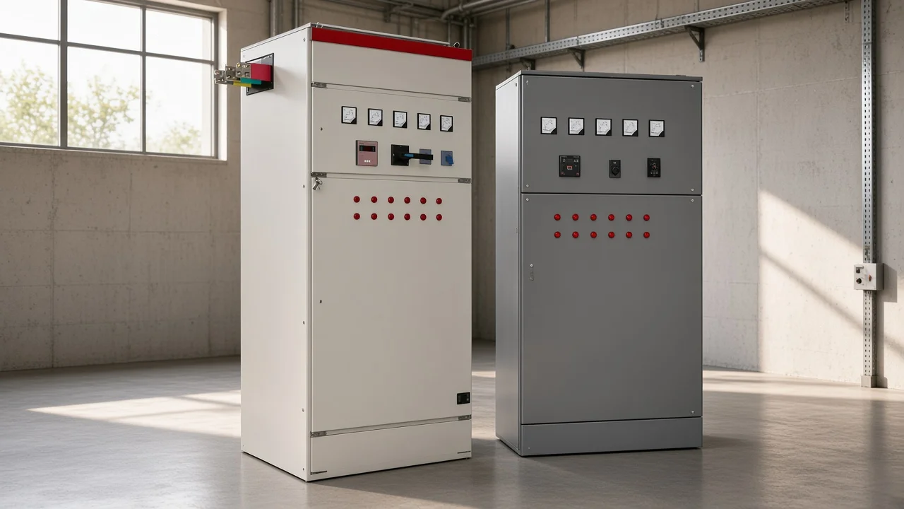
Power factor is the ratio of real power in kilowatts to apparent power in kilovolt-amperes on the bus that serves motors and other inductive loads, so a lagging plant draws more current than the useful work alone would suggest.
Real power is the working power that produces heat, motion, or process output. Reactive power is the magnetizing or wattless component that still loads conductors. Apparent power is the combined demand the transformer and cables must carry.
| Quantity | Unit | Plant role |
|---|---|---|
| Real power | kW | Useful work delivered to the process |
| Reactive power | kVAR | Magnetizing demand from inductive equipment |
| Apparent power | kVA | Total supply burden seen by the transformer and feeders |
| Power factor | kW / kVA | Share of apparent power that is real work |
On a factory main board, motors, transformers, welding sets, and similar inductive loads typically produce a lagging power factor. The current waveform lags the voltage waveform, so the “kVA ticket” is larger than the kilowatt work alone.
That definition is the plant-bus meaning. Keep sizing worksheets and chip-level active-PFC tutorials on their own pages.
Why Low Power Factor Costs Capacity and Raises Current
Low power factor means the same process kilowatts need more apparent power, so transformers and cables carry extra reactive current and utilities may apply charges or incentives around poor PF.
Extra reactive current heats conductors and fills transformer capacity that could otherwise serve new load. A comparatively small improvement in power factor can cut losses because losses scale with the square of current.
Utility tariffs differ by site. Many networks encourage or penalize plants around contracted thresholds often discussed near 0.90–0.95, but the exact dollars belong to the local rate schedule, not to a generic savings claim here.
When a buyer sees high feeder current or a power-factor note on a bill, the first job is to treat lagging plant PF as a capacity and tariff problem. The second job is to decide whether reactive power compensation on the LV side is the right next step.
What Power Factor Correction Changes on the Same Load
Power factor correction supplies leading capacitive reactive power so the supply sees less lagging reactive current for the same useful load, typically aiming near 0.92–0.95 rather than forcing exactly 1.0.
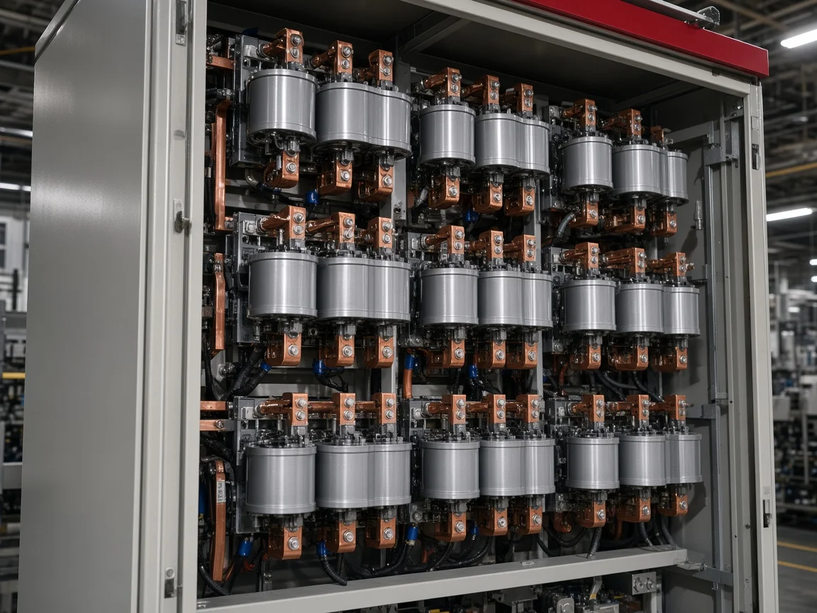
Power factor correction capacitors act as local sources of leading vars. They cancel part of the lagging magnetizing demand from motors and transformers. Process kilowatts stay the same; apparent power and line current fall as the power factor rises.
Industry education commonly targets a corrected band around 0.92–0.95 as economically practical. Forcing exactly unity is not always the plant goal, and overshooting into a strong leading power factor creates its own risks later in this article.
That is what correction changes on the same load. Distorted current waveforms still need filters or redesign.
How Plants Apply Correction with Load, Group, and Automatic Banks
Plants place power factor correction capacitors at individual loads, on group buses, or as automatic banks at a feeder or service entrance, with automatic steps better when load varies.
| Placement | Typical use | Strength | Watch-out |
|---|---|---|---|
| Individual / at-load | Large motors switched with the load | Caps track that machine; less light-load overcorrection | Highest cost per kvar; not for drive outputs |
| Group | Cluster of loads on one bus or room | Shares one bank among several machines | Still needs a plan when the group shuts down |
| Central / automatic power factor correction | Feeder or service entrance with a controller | Tracks plant-wide reactive demand in steps | Upstream placement does little for long feeder losses downstream |
Automatic power factor correction uses a controller that measures reactive demand or power factor and switches capacitor steps in and out. An Automatic / APFC bank is that controller-switched assembly. That approach fits mixed, changing plant loads better than a single fixed bank left energized through a quiet weekend.
From the field: Caps at the main substation mainly correct the path toward the utility; placing banks nearer the electrical rooms or loads is what reduces reactive current on the long feeders themselves — Mike Holt — where to put PF correction capacitors.
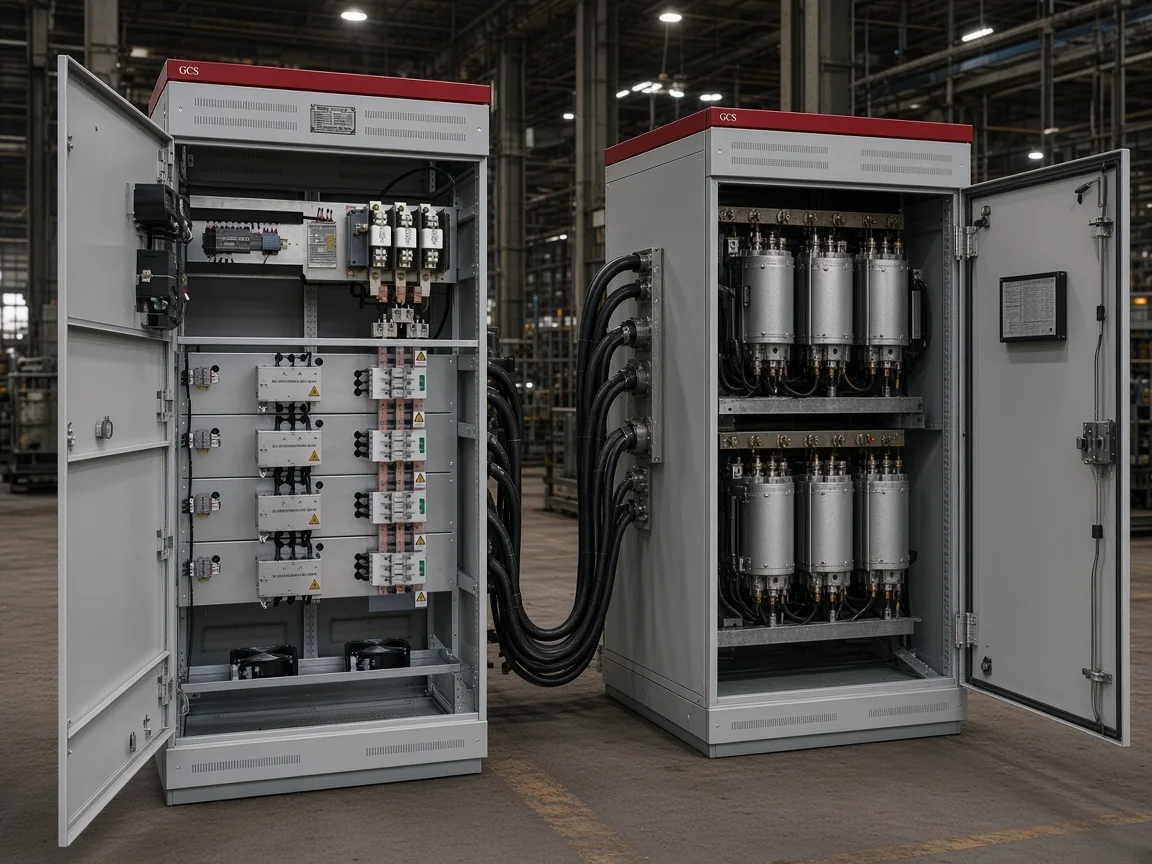
Reactive power compensation is the broader name for that kvar support. The placement choice is a plant decision, not a single catalog SKU.
When Capacitors Are Not Enough for Distortion, Drives, and Overcorrection
Distorted or harmonic-dominated poor PF needs filters or equipment design changes; static capacitors must not sit on VSD/soft-starter/inverter outputs; fixed banks left on at light load can push leading PF and raise voltage.
Displacement power factor is the phase-angle problem from inductive loads. Distortion power factor comes from nonlinear loads such as variable-speed drives, rectifiers, and many electronic supplies. Plain shunt capacitors correct the displacement case; they do not repair a heavily distorted waveform by themselves.
Tip: Do not apply static power factor correction capacitors on the output of a variable speed drive, solid-state soft starter, or inverter — that placement can damage the electronics.
Fixed banks that stay on when the plant is lightly loaded can overcorrect. The bus can go leading, voltage can rise, and lamps or controls may fail early on quiet shifts. Automatic or load-switched stages reduce that risk by removing kvar when the inductive load disappears.
If the site mixes large VFD fleets with motor loads, plan harmonic measurements and detuned or filtered solutions before treating every poor reading as a job for bare capacitors.
How to Choose an LV HYTBBJ or HYTBBD Path After the PF Lesson
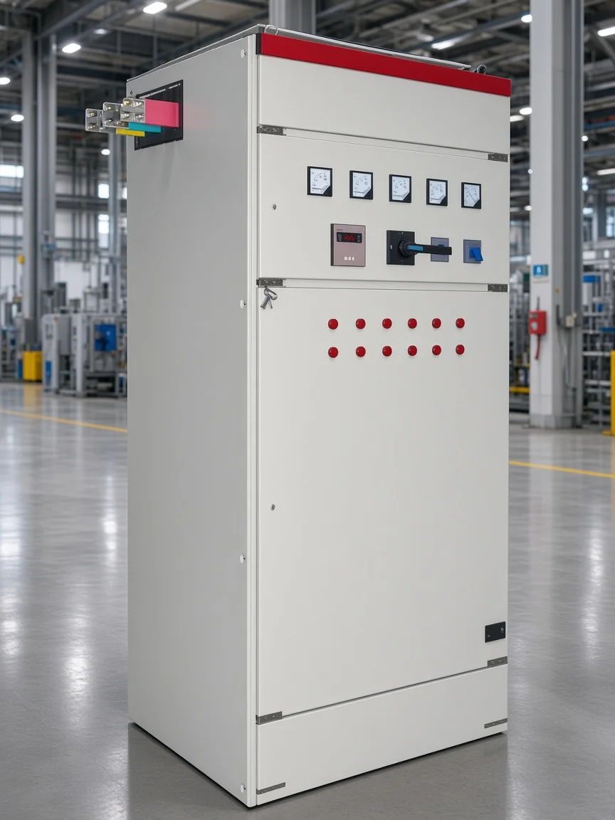
HYTBBJ fits relatively steady inductive loads with automatic capacitor-group switching by reactive demand or power factor; HYTBBD fits large load variation with printed target PF ≥0.95 and 15–60 kvar dynamic groups; the hub lists static, dynamic, outdoor, and end-point options.
The HYTBBJ static LV system is the first-party path for relatively steady inductive loads. Choose the HYTBBJ low-voltage static reactive power compensation system when the plant’s inductive reactive demand is relatively steady in manufacturing, buildings, or public facilities. The printed overview states that HYTBBJ automatically switches capacitor groups according to measured reactive demand or power factor and helps reduce reactive current, improve transformer utilization, and maintain the required power factor.
Printed HYTBBJ features include power factor (reactive current) control with manual and automatic modes. Switching delay is adjustable from 0–120 s, with a special fast mode ≤1 s.
Protections cover over-voltage, under-voltage, over-current, short circuit, capacitor fault, and switching error. The model-code example uses a 0.4 kV system voltage level.
A printed feature line also states that the system reduces harmonic current (typ. 20%–30%) as a product-feature statement for that series.
The HYTBBD dynamic LV system is the first-party path when inductive load swings hard. Choose the HYTBBD Series Low-Voltage Dynamic Reactive Power Compensation System when inductive load varies strongly — for example metallurgy, machinery, mining, building materials, petrochemical, or municipal distribution with large swings. Printed specifications include rated voltage AC380V ~ AC1140V ±15%, rated frequency 50Hz / 60Hz ±4%, target power factor ≥ 0.95, rated capacity per group 15–60 kvar (dynamic switching), environmental temperature −10°C ~ +45°C, relative humidity ≤95% non-condensing, altitude ≤4000 m with derating above 2000 m, and protection level IP30.
The LV PF compensation series hub — Low Voltage Power Factor Compensation Series — frames static, dynamic, outdoor, and end-point low-voltage compensation systems for staged power-factor control in industrial and commercial networks. Use that hub to see neighboring outdoor and end-point options after the steady-versus-fluctuating choice.
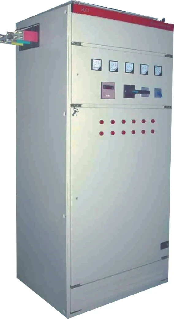
Match the printed steady or fluctuating job, then enquire with measured load behavior and harmonic context. Leave worksheets, listing certificates, and payback calculators outside this shortlist.
What Stays With Calculation and Panel-Design Articles
Capacitor-size and power-factor calculation procedures belong with the sibling how-to-calculate package. Live APFC wiring and panel-design posts already cover control circuits and cabinet layout.
Keep the focus here on the linked meaning of power factor and power factor correction for LV plant decisions.
FAQ
What is power factor in a plant electrical system?
Power factor is the ratio of real power in kilowatts to apparent power in kilovolt-amperes on the plant bus. A lagging value means inductive loads are asking the supply to carry extra reactive current for the same useful work.
What is power factor correction?
Power factor correction is the practice of supplying leading capacitive reactive power — usually with power factor correction capacitors or switched banks — so the utility sees less lagging reactive current while process kilowatts stay the same.
Why does low power factor matter on an LV bus?
Low power factor raises the apparent power needed for the same kilowatts, fills transformer and cable capacity with reactive current, increases I²R losses, and may trigger utility charges or incentives around contracted thresholds.
What is a power factor correction unit?
In plant language, a power factor correction unit is usually an assembled capacitor bank — often with automatic power factor correction control — that switches kvar steps to hold a target band on a feeder or service entrance.
Can capacitors fix every poor power factor?
No. Capacitors address displacement (inductive) power factor. Distorted waveforms from drives and other nonlinear loads need filters or equipment design changes, and static capacitors must not be placed on VSD, soft-starter, or inverter outputs.
When should a plant use an automatic power factor correction bank?
Use automatic power factor correction when plant load varies and a fixed bank would overcorrect at light load or undercorrect at peaks. A controller adds and removes capacitor steps to stay near the target band.
When do HYTBBJ or HYTBBD fit after this lesson?
HYTBBJ fits relatively steady inductive loads with automatic capacitor-group switching by reactive demand or power factor. HYTBBD fits large inductive-load variation, with printed target power factor ≥0.95 and 15–60 kvar dynamic groups under the LV compensation series hub.