
 Zhejiang Hongyan Electric Co., Ltd.






































Yes—is a power factor of 1 possible in the ideal sense, and plants can get very close with good correction. Exact continuous 1.000 on a live feeder is rarer: motors swing, a capacitor bank / PFC switches in steps, and a “1.0” displacement reading can hide a lower true power factor.
This page separates ideal unity from practical targets. It then shows when low-voltage static compensation on the LV Power Factor Compensation Series hub is a logical next step after you set a realistic goal.
For the basic ratio P/S, use the live definition and calculation guides after you finish here. This article stays on whether unity is attainable and how to read the meter honestly.

What a Power Factor of 1 Means
Power factor (PF) of 1 means real power equals apparent power. In plant language that is Real power (kW) equal to Apparent power (kVA) at the metering point; in circuit language it is P = S. Engineers call that state unity power factor.
When voltage and current are in phase on a clean sinusoidal circuit, the phase angle is zero and cos φ equals 1. Reactive power (kVAR) on the power triangle then nets to zero (Electronics Tutorials — Power triangle; Wikipedia — Power factor).
All of the volt-amperes the feeder carries are doing useful work in that ideal case. Below unity, the same real load needs more current—so plants care about the gap between “almost 1” and “0.7-something,” not three more decimal places of perfection.
When Unity Power Factor Is Ideal
A purely resistive load has a power factor of 1. Heating elements, simple resistive process loads, and textbook R-only circuits line voltage and current up so the reactive leg of the triangle collapses to zero (All About Circuits — Calculating power factor; meter help pages state the same for a purely resistive case).
Unity is also the design goal of power-factor correction: add capacitive reactive power that cancels inductive reactive power until the residual angle is near zero. Textbook correction examples often land extremely close to 1.0—sometimes reading about 0.999 lagging—when the parallel capacitor is sized carefully (All About Circuits).
So the short answer to “is unity possible?” is yes under ideal resistive conditions, and yes as a corrected target when the load behaves. The longer answer is what happens when the plant is not a single resistor.

Why Exact 1.000 Is Rare on Real Plants
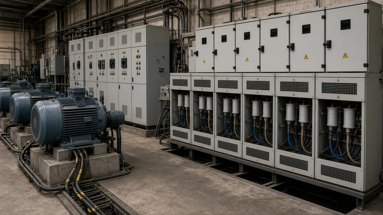
Motor-heavy plants rarely see a natural power factor of 1. Induction motors, transformers, and welding plant draw lagging current; industry guidance notes that a natural unity factor is rarely achieved with those loads installed (BEAMA Guide to Power Factor Correction).
Even after you add automatic capacitors, exact continuous 1.000 is hard. Controllers switch kvar in discrete steps while motor load drifts in an analog way. Unless stages are infinitely fine, the reading walks around the setpoint.
Plant engineers on engineering forums describe unity with stepped banks as virtually impossible in practice. They also warn that exact inductive–capacitive balance can invite resonance and circulating currents—enough, in reported cases, to nuisance-trip large breakers on modest real loads (CR4 — Theory of Power Factor @ Unity).
Oversizing capacitors creates a different problem: the circuit can go leading. Too much capacitance lowers power factor again, just on the other side of unity (All About Circuits).
Choosing a Practical Target Instead of Forcing 1.0
Many plants aim near 0.95 rather than forcing exact unity. That “cushion” language shows up repeatedly in practitioner threads: leave headroom against overshoot, resonance, and sudden motor starts, because the loss difference between 0.95 and 1.0 is often small relative to the control risk (CR4 unity discussion).
Treat ~0.95 as common engineering conversation—not a universal utility law. Some rate schedules care about average monthly power factor, some about peaks, some not at all. Read the tariff instead of inventing a fine.
From the field: When site staff manually force every capacitor stage online during a shutdown, they can sometimes push the meter to unity for a quiet base load—and that is exactly when the conversation starts about whether chasing 1.000 is wise once production returns (CR4 — Theory of Power Factor @ Unity). A stable target with a cushion usually beats a brittle “always 1.00” setpoint.
| Condition | Typical PF story | Practical takeaway |
|---|---|---|
| Pure resistive process | Near or at 1.0 without capacitors | Unity is natural |
| Motor / transformer mix, uncorrected | Often well below 1.0 | Natural unity rare |
| Stepped automatic capacitor bank | Can approach unity; may hunt | Leave a control cushion |
| Nonlinear / VFD-heavy mix | Displacement may look fine while true PF lags | Check harmonics before celebrating 1.0 |
If you need the arithmetic for converting kW and kVA into a decimal, use the how to calculate power factor guide. For what the ratio means in an AC circuit, see what is power factor in an AC circuit.
Displacement vs True Power Factor Under Harmonics
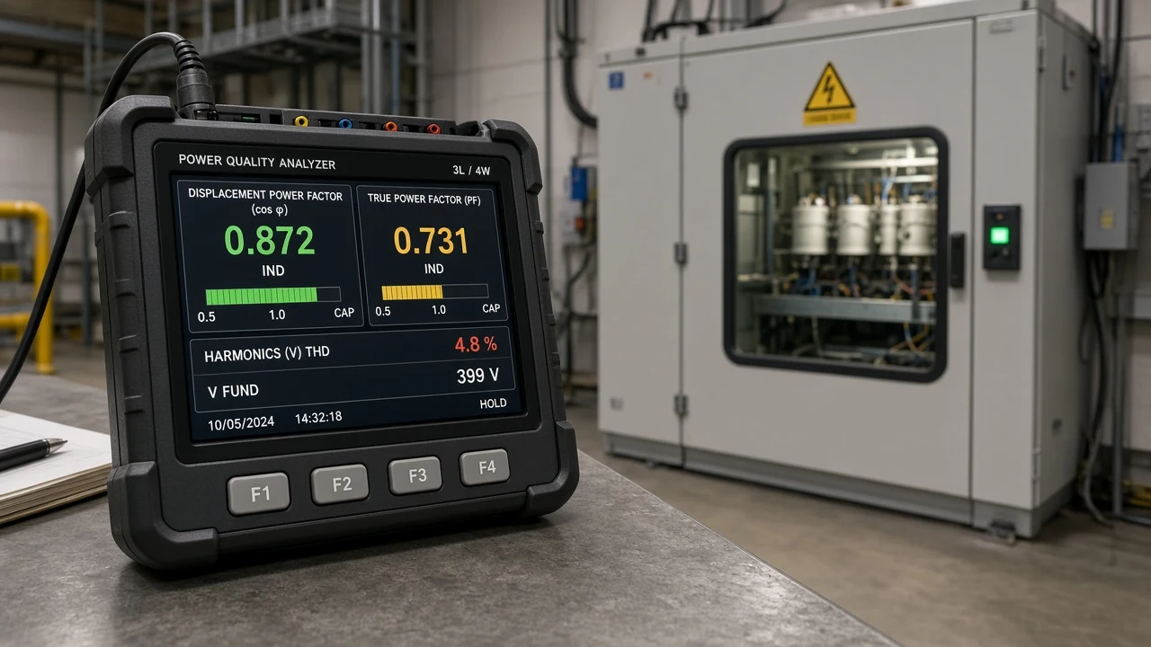
Displacement power factor looks at the fundamental voltage–current angle. True power factor is real power divided by apparent power and includes harmonic content.
Modern meters often default to true power factor unless the display is labeled otherwise (Schneider Electric PowerLogic measurement help — true vs displacement PF). That is a measurement definition, not a claim that any particular meter model is installed on your site.
Harmonics / THD change the story. Distorted current raises RMS amperes—and therefore apparent power—without adding much real power.
A published educational example shows displacement power factor at 1.000 while true power factor sits at 0.531 under very high current THD (about 156%). Real power was roughly 86 W against 162 VA of apparent burden (Power Monitors, Inc. — Understanding How Harmonics Affect Power Factor).
| Reading | What it includes | Why it can mislead |
|---|---|---|
| Displacement PF ≈ 1.0 | Fundamental phase alignment | Looks “perfect” while harmonics still inflate VA |
| True PF ≪ 1.0 | Full P/S with distortion | Shows the feeder burden the displacement reading hid |
Capacitors can restore displacement power factor toward unity by canceling fundamental reactive power, yet leave the harmonic contribution in place. Adding capacitors on a distorted bus can also raise harmonic levels through resonance, so measure harmonics before and after correction (PMI harmonics and power factor white paper).
Important: A meter that flashes “1.00” on displacement alone is not a green light to stop looking. Ask which power factor the instrument is showing, and whether current distortion is part of the load mix — source: PMI harmonics and power-factor note.
Where LV Static Compensation Fits After You Set a Target
Once you accept that unity is ideal, that exact continuous 1.000 is uncommon, and that true PF can lag a cheerful displacement reading, the equipment question becomes practical: can a stepped low-voltage bank hold a stable target on a relatively steady inductive feeder?
For that steady inductive case, the HYTBBJ Series Low-Voltage Static Reactive Power Compensation System is published to switch capacitor groups from measured reactive demand or power factor. The page scopes it to manufacturing, buildings, and public facilities where inductive demand stays relatively stable.
It helps reduce reactive current, improve transformer utilization, and maintain the required power factor. Control can follow power factor (reactive current) in manual or automatic modes.
Real-time monitoring covers three-phase voltage, current, power factor, and compensation status. The published model-code table includes a 0.4 kV system voltage level.
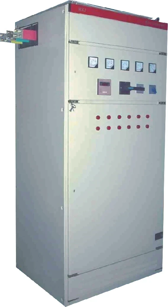
That product story is not a promise of continuous PF = 1.000. It fits plants that chose a realistic target and need staged switching on measured power factor.
Highly swinging loads may need a dynamic series instead. Browse the LV Power Factor Compensation Series for static, dynamic, outdoor, and end-point options. Do not treat catalog pages as UL/NEC listings, savings guarantees, or payback calculators.
FAQ
Is a power factor of 1 possible?
Yes in the ideal sense: a purely resistive load sits at unity, and carefully corrected circuits can approach 1.0. Exact continuous 1.000 on a motor-heavy plant with stepped capacitors is uncommon.
Can PF be greater than 1?
No as a magnitude of real power over apparent power—real power cannot exceed apparent power. A “leading” reading means capacitive reactance, not a value above 1.0.
Is 0.9 power factor good?
Often workable for many industrial conversations, especially when a plant is leaving a cushion below exact unity. Whether it is “good enough” still depends on your utility rules and feeder capacity—not a universal grade.
Is a power factor of 0.7 good?
Usually not for industrial feeders: the same real load needs substantially more current, and many tariffs treat that range as poor. Confirm against your rate schedule rather than assuming a fixed fine.
Why is a power factor of 1 considered perfect?
Because real power equals apparent power and the reactive burden is zero in the ideal case—every ampere contributes optimally to useful work.
Can displacement power factor be 1 while true power factor is lower?
Yes. Under high harmonic current, displacement PF can read 1.000 while true PF is much lower, as in published educational examples. Ask which quantity your meter displays.
Should I chase exact 1.0 with capacitor banks?
Many practitioners prefer a cushion near ~0.95 to reduce overshoot and resonance risk. Measure harmonics before and after adding capacitors, especially on nonlinear loads.
When does LV static compensation fit after I set a PF target?
When the load is relatively steady and inductive, and you need automatic switching of capacitor groups from measured reactive demand or power factor—such as the HYTBBJ static series on the LV compensation hub.
References
- Wikipedia encyclopedia entry on power factor
- Electronics Tutorials guide to the AC power triangle
- All About Circuits textbook chapter on calculating power factor
- PMI white paper on how harmonics affect power factor
- CR4 engineering thread on theory of power factor at unity
Humanizer self-audit (Author)
- Pass 1: removed stacked “Is X possible? Yes…” openings on every H2; varied paragraph length; kept educational PMI numbers labeled as published example.
- Pass 2 (“what still sounds AI?”): cut meta-process wording; avoided claim-ID leakage; no invented tariff/payback/UL; soft ~0.95 as practitioner language not law.
- Facts preserved from research claims C-01–C-16 only; no new numeric inventions.
- Second self-pass owner: CHYN-DFT-PF1-20261025-02