
 Zhejiang Hongyan Electric Co., Ltd.






































A capacitor required to improve power factor is the plant answer when lagging inductive loads—motors, transformers, and similar equipment—pull magnetizing reactive power that you should supply locally instead of asking every feeder and the utility to carry it. Capacitors (or switched capacitor banks / APFC stages) inject leading vars that cancel that lagging demand, raise displacement versus true PF clarity on what caps can fix, and free apparent-power capacity.
This guide covers when that capacitor is required, what kvar required for power factor means at an intuition level, when a fixed vs automatic capacitor bank fits, and the pitfalls that turn a good correction into a leading-power-factor headache—before you buy. Power factor correction capacitors remain the standard tool for that lagging inductive job.
For the full kvar worksheet, bank hardware framing, PF definition, PF math, and the three PF types, use the live how to calculate kvar for a capacitor bank, capacitor bank for power factor correction, power factor and power factor correction, how to calculate power factor, and 3 types of power factor pages after you finish the need decision here.

When a Capacitor Is Required to Improve Power Factor
A capacitor is required when your bus shows lagging displacement power factor driven by inductive loads and you need to supply that reactive power (kvar) closer to the load.
Induction motors, transformers, and similar equipment draw magnetizing current that lags voltage. That reactive demand raises apparent power (kVA) for the same real work (kW), so cables, transformers, and generators carry extra current (IET — Power Factor Correction; U.S. DOE — Reducing Power Factor Cost).
You typically decide capacitors are required when one or more of these show up together:
- Meters or billing reports show lagging PF below the target your tariff or internal policy cares about (many utilities flag values below about 0.95—treat that as a common educational threshold, not a universal law) (DOE fact sheet).
- Transformer or feeder loading is dominated by reactive current you could cancel locally.
- The load mix is clearly inductive (motors, welding, furnaces) rather than a harmonic-distortion story alone.
| Situation | Capacitor-based correction? | Why |
|---|---|---|
| Lagging PF from motors / transformers | Usually yes | Caps supply leading vars that offset inductive demand (IET) |
| Utility or capacity pressure on lagging PF | Often yes | Local kvar reduces the reactive burden on the supply (DOE) |
| Poor “true” PF dominated by harmonics / discontinuous current | Not capacitors alone | Distorted waveforms need filtering or equipment design change; capacitors address displacement PF (IET) |
| Bus already leading from excess capacitance | No—remove or reduce caps | Adding more capacitors worsens leading PF |
Power factor correction capacitors are therefore the standard tool for lagging inductive displacement PF—not a universal bandage for every low reading on the meter.
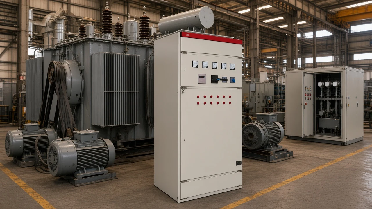
What “kvar Required” Means (Sizing Intuition)
“kvar required” is the reactive power your capacitor bank must supply so the net vars—and therefore the power factor—move from today’s lagging angle to the target angle. The industry sizing intuition is:
Qc = P × (tan φ1 − tan φ2)
where P is real power in kW, φ1 is the existing power-factor angle, and φ2 is the target angle. In plain language: required kvar is the gap between the reactive power you have now and the reactive power you want after correction. Community metering threads make the same literacy point: volt-amperes are not watts, so power factor only becomes trustworthy after you separate real and apparent power (EEVblog — electronics math and power factor).
Educational illustrations help lock the scale without pretending to be your plant study.
The U.S. DOE Motor Challenge fact sheet walks a 100 kW inductive load at 0.70 power factor up to about 0.95. After adding on the order of ~67 kvar of capacitance, apparent power falls from about 142 kVA to about 105 kVA (DOE).
Schneider’s public FAQ uses the same formula on a 1000 kW example from cos φ 0.8 to 0.95 and lands at 420 kvar. That is order-of-magnitude thinking, not a certificate for your switchboard.
Most industrial guidance aims for roughly 0.92–0.95 lagging rather than forcing brittle unity (IET). Chasing 1.000 with stepped banks under swinging load is how plants overshoot into leading territory.
For the step-by-step worksheet, measurement tips, and worked tables, stay on how to calculate kvar for a capacitor bank. This section only answers what “kvar required” means so you know what you are shopping for.
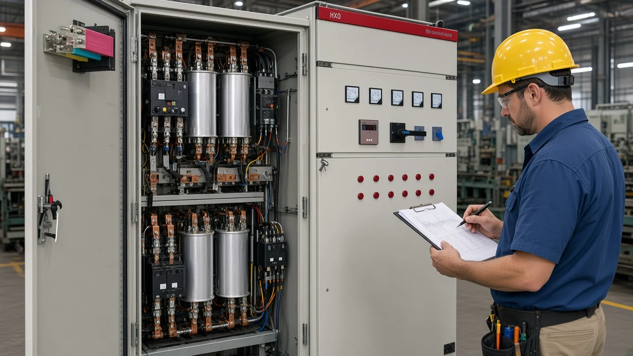
Fixed Capacitors vs Automatic Capacitor Banks
Once you know capacitors are required, the next decision is how those kvar stages switch.
| Approach | Best when | Watch-outs |
|---|---|---|
| Fixed capacitor (always on or tied to one load) | Continuous, predictable inductive demand—steady conveyors, fans, transformer magnetizing compensation | Light-load periods can overcorrect if the stage cannot drop offline |
| Individual motor capacitor | One large motor that runs long hours with a known magnetizing need | Size from no-load / magnetizing reactive demand, not full-load nameplate alone; never on VFD/soft-starter outputs (IET) |
| Automatic capacitor bank / APFC | Plant kvar need moves with shift patterns, batch lines, or many motors cycling | Needs correct CT/PT sensing and a sensible target (often ~0.95); still respect harmonics |
IET guidance distinguishes static correction at a motor starter from bulk correction at the origin of the installation, where a controller monitors vars and switches capacitor steps to hold a preset limit (IET). Engineering forum practice echoes the same split: fixed banks for relatively constant continuous loads; automatic regulation when the required compensation is large relative to the supply or the load varies. Treat any Qc/transformer-size percentage rule as a conversation starter with your engineer—not a CHYN design standard.
If the load is steady, a staged static cabinet that switches groups from measured power factor can still be “automatic” at the group level without implying a fully dynamic thyristor system. If the inductive demand swings hard, you want faster or more granular switching—and you should say that out loud before you buy.
Pitfalls: Overcorrection, VFDs, and Harmonics
Capacitors solve lagging inductive demand. They create new problems when misapplied.
Overcorrection / leading PF. Too much capacitance relative to the remaining inductive load flips the bus leading and raises voltage. Plant engineers have described weekend or light-load periods where banks left online against nearly lighting-only demand drove voltage high enough to stress lighting and other equipment. The fix is usually to drop stages, raise controller deadband, or stop forcing manual “all on”—not to add another rack of capacitors.
From the field: If every stage stays forced online after the process line stops, the meter can swing from lagging into leading and the bus voltage can climb. That is overcorrection, not “extra improvement.” — source: IET Power Factor Correction over-correction caution plus DOE capacity/voltage framing.
Never put static PFC capacitors on a VFD / soft starter or inverter output. IET guidance is explicit: capacitors on those terminals can damage the electronics (IET). Correct upstream of the drive or with a topology designed for that environment.
Harmonics. Capacitors fix displacement PF from linear inductive loads. When nonlinear loads distort current, true power factor can stay poor even if the fundamental angle looks fine—and plain capacitor banks can participate in resonance. That path belongs to harmonic studies and filtering, not “add more kvar.”
Wrong capacitor type. Power-factor work needs AC-rated PFC capacitors. Scavenged DC electrolytics from computer power supplies are the wrong device class for AC line correction—community threads keep rediscovering that the hard way.
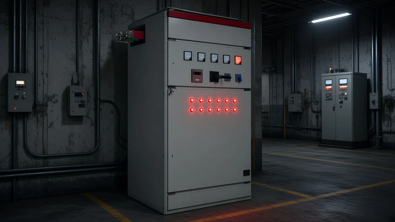
Decision Checklist Before You Buy Capacitors
Use this short gate before you issue an RFQ:
- Confirm the need is lagging inductive displacement PF—not a harmonic-only true-PF complaint and not an already-leading bus.
- Estimate kvar required with Qc = P × (tan φ1 − tan φ2) from measured kW and existing/target PF; refine with the kvar calculation guide.
- Pick the switching mode: fixed / motor-mounted for steady continuous demand; automatic group switching when kvar need moves with the process.
- Scan pitfalls: light-load overcorrection, VFD/soft-starter output terminals, harmonic resonance risk, AC-rated equipment only.
- Set a practical target near 0.92–0.95 lagging unless your tariff or engineer says otherwise—do not treat unity as a brittle setpoint.
- Match the product family to load steadiness (next section) and collect voltage, load mix, existing compensation, and harmonic notes for the enquiry.
If you cannot clear step 1, stop shopping for capacitors and reopen the measurement.
Which LV Capacitor Compensation Fits After You Decide
After the need decision, look at the Low Voltage Power Factor Compensation Series hub.
For relatively steady inductive loads in manufacturing, buildings, and public facilities, the HYTBBJ Series Low-Voltage Static Reactive Power Compensation System automatically switches capacitor groups according to measured reactive demand or power factor. It uses power-factor (reactive-current) control with manual and automatic modes, monitors three-phase voltage, current, and power factor, and the published model code includes a 0.4 kV system voltage level. That is a natural next fit when you have already decided capacitors are required and the kvar demand does not thrash every minute.
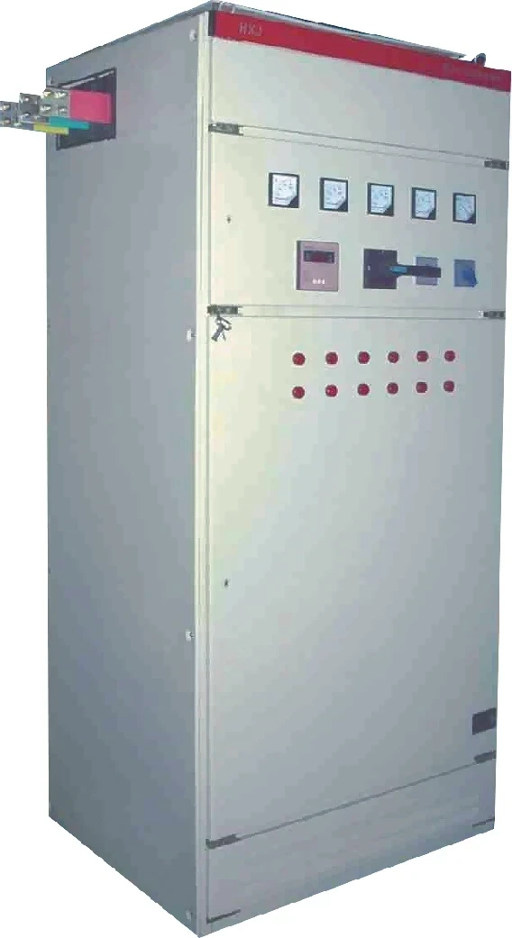
When inductive load varies strongly—metallurgy, mining, batch machinery, and similar swinging feeders—the HYTBBD Series Low-Voltage Dynamic Reactive Power Compensation System is positioned for real-time reactive compensation with a printed target power factor ≥ 0.95.
Bring voltage, load mix, existing compensation, and harmonic notes when you enquire. These families answer which CHYN LV capacitor-compensation cabinet fits after you know capacitors are required.
FAQ
Is a capacitor required to improve power factor?
Yes when lagging inductive loads create displacement power factor problems you need to correct locally. Capacitors supply leading reactive power that offsets magnetizing demand (IET; DOE). They are not required—and can hurt—when the bus is already leading or when the complaint is mostly harmonic distortion.
How much kvar is required to improve power factor?
Use Qc = P × (tan φ1 − tan φ2) with measured real power and existing/target power factors. Educational examples (for scale only) include ~67 kvar to move 100 kW from 0.70 to about 0.95 (DOE). Full measurement and table work lives on the kvar calculation article.
Is 0.9 or 0.95 a good power factor target?
Many guides and utility conversations cluster around 0.9–0.95. IET notes typical corrected values around 0.92–0.95; DOE notes many utilities charge additional fees below about 0.95. “Good” still depends on your tariff and plant constraints—open the rate schedule before treating any number as law.
Should I use a fixed capacitor or an automatic bank?
Fixed (or motor-mounted) stages fit continuous, predictable inductive demand. Automatic banks fit varying plant kvar need. IET describes both static motor correction and controller-switched bulk banks (IET).
What happens if I oversize the capacitor bank?
Excess capacitance can push a leading power factor and raise bus voltage—especially at light load when stages stay online. Drop stages or retune the controller; do not keep adding capacitors.
Can I put power factor capacitors on a VFD output?
No. Do not apply static power-factor correction capacitors on the output of variable-speed drives, solid-state soft starters, or inverters (IET).
Do capacitors fix poor power factor caused by harmonics?
Not by themselves. Capacitors correct lagging displacement PF from inductive loads. Distorted current waveforms need filtering or equipment changes (IET).
When does HYTBBJ vs HYTBBD fit?
HYTBBJ fits relatively steady inductive loads and switches capacitor groups from measured reactive demand or power factor (0.4 kV in the published model code). HYTBBD fits large inductive-load variation with a printed target power factor ≥ 0.95. Start from the LV power factor series hub.
References
- IET — Power Factor Correction (Wiring Matters PDF) — lagging inductive loads, capacitor correction, typical 0.92–0.95 targets, motor vs bulk application, VFD/soft-starter prohibition.
- U.S. Department of Energy — Reducing Power Factor Cost (Motor Challenge fact sheet) — why low PF costs capacity and often incurs utility fees; educational capacitor sizing triangle.
- Wikipedia — Power factor — definition of power factor and lagging/leading phase language supporting the need decision.
- EEVblog forum — electronics math and power factor — community reminder that VA ≠ watts and PF needs real vs apparent power separated.