
 Zhejiang Hongyan Electric Co., Ltd.
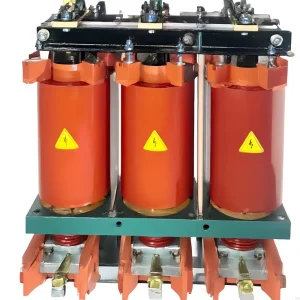
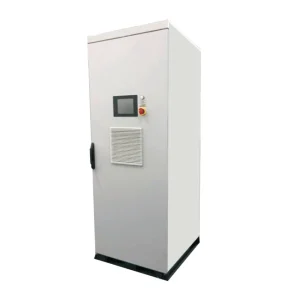
Motor starting voltage drop must be assessed together with starting torque and acceleration time. Limiting current can reduce the disturbance imposed on the supply, but a motor still needs enough accelerating torque to reach its operating speed. A lower current setting that prevents acceleration can extend the starting duty and create a different problem. Begin with the motor data, driven-load characteristic, source conditions and measured voltage at both the supply bus and motor terminals. Then evaluate the starter and protection as one coordinated system.
This guide focuses on the information needed for a starting study and a medium-voltage soft-starter inquiry. It does not prescribe live adjustments or universal current-limit settings.
Distinguish supply-bus voltage from motor-terminal voltage
Voltage drop depends on where it is measured. A large motor start may depress the shared bus and affect other equipment. Additional drop along the motor feeder can reduce the voltage available at the motor terminals. Record both locations when practical, with synchronized current and voltage channels, so the study can separate source behavior from feeder effects.
Include the actual supply configuration. Transformer rating and impedance, feeder impedance, available fault level and other connected loads influence the response. A generator-backed operating mode requires its own assessment because its dynamic response can differ from the utility supply. A starter selected for one source condition should not automatically be accepted for another.
Plot the whole start rather than retaining only the lowest voltage. The initial dip, recovery, acceleration period and transition to normal running each provide useful information. Record whether neighboring drives, contactors or control supplies operated abnormally at the same time.
Why reducing current also affects torque
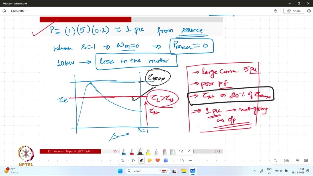
Reduced-voltage starting changes the motor’s available torque. The U.S. Department of Energy’s guidance on off-design motor voltage explains that reduced voltage lowers torque capability through the accelerating range and can increase acceleration time. The actual outcome depends on motor and load characteristics.
For an induction-motor comparison at the same frequency and slip, torque is commonly approximated as proportional to voltage squared. Use this as a screening relationship, with the motor manufacturer’s curves and the actual starter behavior governing detailed evaluation. A phase-controlled waveform and changing speed make a real start more complex than a single percentage calculation.
An illustrative 0.8 pu motor-terminal voltage gives a torque factor of approximately 0.8² = 0.64 relative to the corresponding full-voltage condition. That does not mean the motor develops 64 percent of rated torque throughout its start. The reference is the full-voltage torque at the same operating point, and the driven load must still be considered.
Compare motor torque with the driven load
The motor accelerates when its developed torque exceeds the opposing load torque by enough to accelerate the combined inertia. Obtain the motor torque-speed curve and the driven-equipment load curve. Include process conditions such as a loaded conveyor, pump head, compressor pressure or a high-inertia fan. A description such as “pump application” is not a complete starting requirement.
A current limit that works for an unloaded test can fail with the real process connected. Conversely, a successful start at one temperature or process condition may not represent the limiting case. Identify the credible worst operating state and ask the equipment owners to confirm it in writing before final starter selection.
NPTEL’s Electrical Machines course includes motor torque characteristics and starting methods. These fundamentals explain why the current setting, voltage profile and load curve must be reviewed together. They do not provide a ready-made setting for a particular installation.
Build a study input sheet
The following original checklist organizes the information needed for engineering review. It is a decision table rather than a list of acceptable numeric limits; each project needs its own approved values.
| Input group | Required information | Question it resolves |
|---|---|---|
| Motor | Nameplate, starting current and torque curves, thermal starting limits | Can the motor accelerate within its permissible duty? |
| Driven load | Torque-speed curve, inertia and starting process state | What accelerating torque is required? |
| Source | Transformer or generator data, impedance and operating configuration | How much does the supply respond during starting? |
| Feeder | Cable arrangement, length, impedance and connection details | What voltage reaches the motor? |
| Other equipment | Critical-load sensitivity and shared-bus operating states | Which neighboring loads must remain operational? |
| Starting duty | Cold and hot starts, starts per operating period and restart sequence | Does repeated operation remain inside equipment limits? |
Mark estimated values explicitly. A study using an assumed source impedance can be useful for early comparison, but the assumption needs confirmation before it becomes a purchase guarantee. Keep the data revision and the person responsible for each input with the worksheet.
Use simple calculations only within their limits
For an illustrative three-phase balanced screening calculation, a feeder voltage-drop estimate can be expressed as ΔV ≈ √3 I(R cosφ + X sinφ), using compatible units and impedance for the relevant conductor path. The result is an approximate line-to-line drop in volts. The current, power factor and source voltage change during starting, so one constant-current result cannot describe the complete event.
Suppose a hypothetical current of 300 A, R = 0.02 Ω, X = 0.04 Ω, cosφ = 0.3 and sinφ ≈ 0.954 are used for a single operating point. The estimated drop is approximately 23 V. These invented teaching inputs are not site data or a permissible voltage-drop recommendation. They show why reactive impedance and starting power factor matter.
Use a time-dependent starting study when the application requires it. The model should represent the available motor torque, load torque, inertia and supply response. Review the predicted current, voltage and acceleration time against the relevant equipment limits. Record the model’s assumptions so commissioning can test the important ones.
Review protection and starting duty together
A slow or failed acceleration can expose the motor and starter to substantial thermal duty. Obtain the permissible start time, cold and hot starting capability and restart restrictions from the relevant manufacturers. Coordinate these with the protection study. Increasing a trip delay to make a difficult start succeed is not a substitute for demonstrating safe motor and starter operation.
Also investigate the cause of repeated starts. A process control sequence, a mechanical problem or an upstream disturbance can create a duty beyond the original design. Review time-stamped command, speed, current and alarm records before treating the starter as the sole cause.
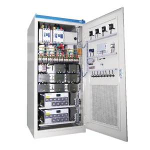
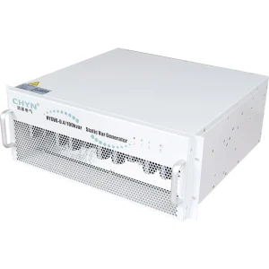
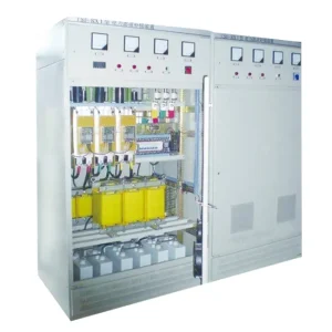
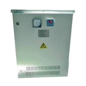
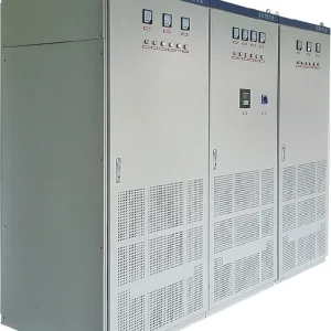
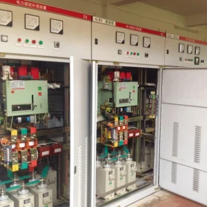
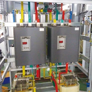
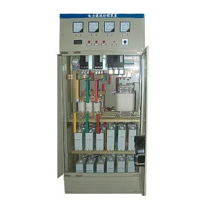
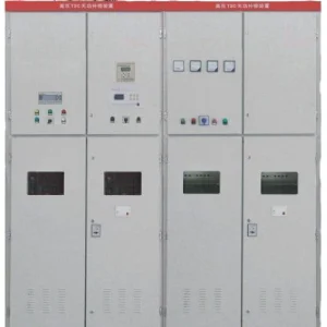
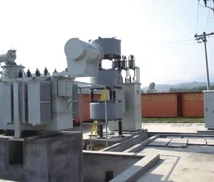
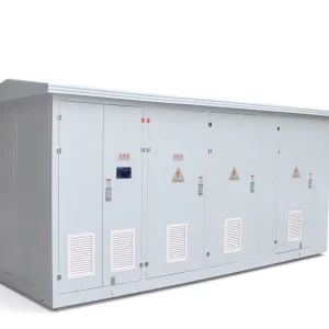
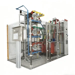
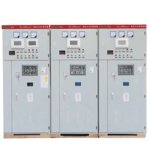
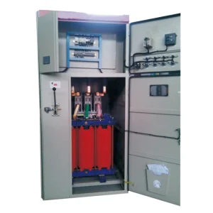
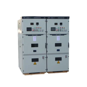
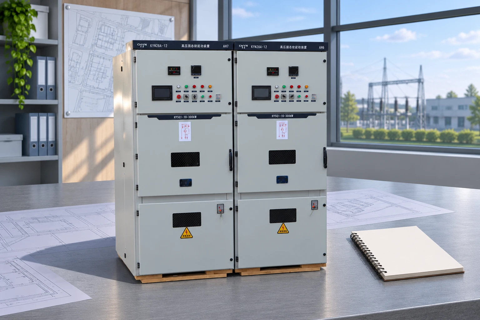
For a CHYN HYSQ1 medium-voltage solid-state soft-starter inquiry, provide the completed data sheet and operating envelope. Ask for configuration-specific selection, thermal-duty confirmation and the required protection interfaces. Product-family information alone cannot establish suitability for the motor.
Commission against the approved prediction
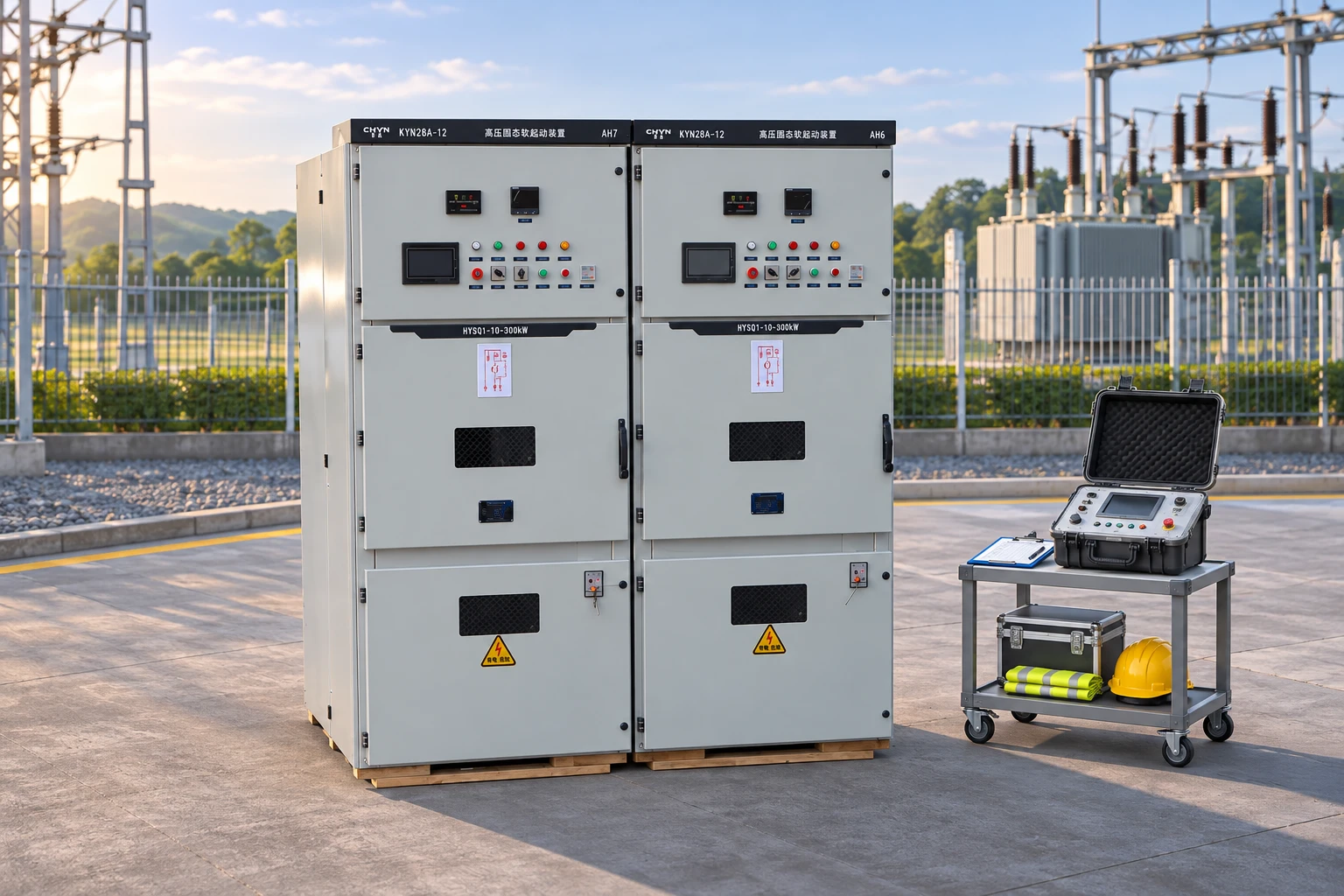
Agree the test conditions before energization. Commissioning should be performed by qualified personnel using an approved procedure, suitable instruments and the required electrical precautions. Capture the actual source configuration, motor load state and equipment settings with each test record. This makes comparison with the study meaningful.
Compare bus voltage, motor-terminal voltage, current profile, acceleration time and process behavior. If the motor accelerates but adjacent equipment trips, the supply disturbance criterion has not necessarily been satisfied. If the shared bus remains stable but the motor cannot accelerate, investigate the motor-terminal conditions and torque margin.
Document deviations and resolve them through engineering review. A revised setting should have a stated reason and should remain inside the motor, starter and protection limits. Preserve the successful baseline as well as failed-start evidence, because later changes in process loading may require another assessment.
Related planning questions
Start with CHYN’s power quality problem overview when identifying the wider disturbance context. The medium-voltage soft starter versus VFD comparison addresses the choice between starting control and operating-speed control. For neighboring automation loads, the PLC voltage sag guide provides a complementary investigation path.
Educational video: induction-motor starting
“Starting and Speed Control of Induction Motor” from NPTEL IIT Delhi explains starting principles and the relationship with motor behavior. It is educational background for the study, not an instruction to modify an energized medium-voltage installation.
Watch Starting and Speed Control of Induction Motor on YouTube.
Keep an operating envelope for future changes
Retain the successful start record with the motor and starter identification, load state and source configuration. When a feeder is lengthened, the driven load changes or a generator operating mode is introduced, compare the change with this baseline. The original successful test is useful evidence only for the conditions it represented.
Include the start command and the indication used to establish that acceleration has completed. Current alone can be difficult to interpret without speed or process information. A clear completion definition allows operators and engineers to recognize a start that has become slower or more demanding before repeated failed attempts obscure the original pattern.
Frequently asked questions
Will a lower current limit always reduce the starting problem?
No. It may reduce the initial supply disturbance while also reducing available accelerating torque. The motor must still reach operating speed within its permissible duty. Review the voltage profile, load torque, acceleration time and protection together before approving a setting.
Where should starting voltage be measured?
Measure at the locations needed to distinguish supply response from feeder drop, commonly the shared bus and motor terminals. Record synchronized current and the actual source configuration. One unlabeled minimum-voltage value cannot explain the whole starting event.
Can an unloaded successful start prove full-load suitability?
No. The driven equipment may require a different torque profile under actual process conditions. Identify the credible limiting starting state and verify it against the motor curves, source conditions and thermal constraints. Document any commissioning cases that remain untested.
Can a utility-supply study be reused for generator operation?
Only after review confirms that the assumptions remain valid. Generator voltage and frequency response can differ from a utility source. Provide the actual generator data and operating conditions, and evaluate the complete start under the alternative source configuration.