
 Zhejiang Hongyan Electric Co., Ltd.
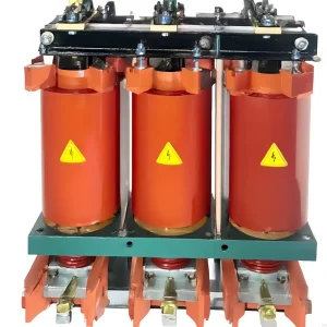
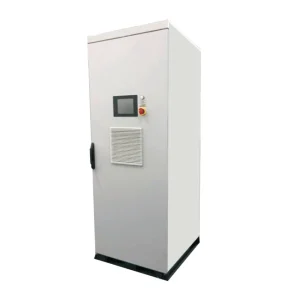
Three-phase current imbalance compensation begins by identifying the cause and the measurement boundary. Unequal phase currents can arise from unequal single-phase loading, an unbalanced supply, a connection defect or equipment behavior. Neutral harmonic current is a related but different issue. Record simultaneous phase voltages, phase currents, power and the relevant operating states before selecting a compensator. Then define the improvement required at a named location and confirm that the proposed device can perform that duty within its documented capability.
This guide is for distribution and industrial project teams comparing load redistribution, fault correction and electronic compensation. It does not offer a universal imbalance limit or claim that one product solves every source of asymmetry.
Distinguish three different observations
Current imbalance describes differences among phase-current quantities. Voltage unbalance describes asymmetry in the three-phase voltage system. A large neutral current can include fundamental imbalance and harmonic components. These observations need different measurements, and a single panel-meter percentage cannot explain all of them.
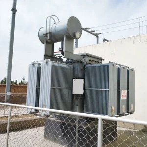
Begin with a diagram showing the transformer, feeders, major three-phase loads and single-phase branches. Mark the measurement location and whether the system is three-wire or four-wire. A result at a motor terminal has a different meaning from a result at the transformer secondary serving many unrelated loads.
Also identify the quantity being reported. An instrument may calculate a sequence-component ratio or a magnitude-deviation index. Those methods are not automatically interchangeable. Record the formula, channel configuration and averaging interval so that a second engineer can reproduce the result.
Use synchronized measurements
Measure all relevant phase quantities during the same interval. Comparing a phase-A reading taken during production with a phase-B reading taken after a load has stopped can create an apparent imbalance that never existed at one moment. A synchronized power-quality recorder helps establish the real relationship between loading and voltage.
Capture operating states that represent the problem: shift changes, heavy single-phase loads, motor starts, distributed generation and different feeder configurations where applicable. Include event logs and the operating schedule. The goal is to identify when the limiting condition occurs and which loads or network states accompany it.
Validate instrument setup before interpreting the result. Confirm CT ratios, polarity, phase association and the voltage connection arrangement using the approved measurement procedure. A configuration error can resemble a physical power-quality problem and should be excluded before equipment selection.
Understand sequence components without overusing them
Symmetrical-component analysis separates a three-phase fundamental-frequency set into positive-, negative- and zero-sequence components. The positive sequence follows the normal phase order; the negative sequence has the opposite order; the zero sequence is common to the phases. The method includes phase-angle information that a simple comparison of three RMS magnitudes can miss.
Janitza’s instrument documentation describes these components and the negative-to-positive voltage-sequence ratio. Use the actual instrument’s definition when reporting measurements. A ratio calculated for voltage must not be relabeled as a current-imbalance result.
For an illustrative calculation, if the positive-sequence voltage magnitude is 230 V and the negative-sequence magnitude is 2.3 V, the ratio is 2.3/230 × 100 = 1 percent. These are teaching inputs. The result is a voltage-sequence metric, not an automatic acceptance limit or evidence that a motor is adequately protected.
Choose the investigation path from the evidence
The following original decision table connects observations with checks. It is intended to guide a site review rather than diagnose a fault from one symptom.
| Observation | Useful evidence | First review direction |
|---|---|---|
| Unequal currents with changing single-phase loads | Phase power and branch load schedule | Review load allocation and variation over time |
| Motor current asymmetry with voltage unbalance | Motor-terminal voltages and synchronized current records | Review supply, connections and motor condition |
| High neutral current with nonlinear loads | Neutral spectrum and phase harmonic spectra | Separate harmonic duty from fundamental imbalance |
| Imbalance appears after maintenance | Drawings, work record and verified instrument setup | Check changes and connection integrity |
| Compensation demand varies rapidly | Time-resolved load and device records | Define dynamic duty and capability limits |
Keep the conclusion proportional to the evidence. An unequal loading pattern may suggest redistribution, but a faulty connection requires correction. A compensation proposal should not conceal an unresolved defect in the supply path or the load.
Why motor-terminal voltage needs attention
The U.S. Department of Energy’s voltage-unbalance tip sheet explains that voltage unbalance can produce disproportionate motor-current unbalance and adverse heating and mechanical effects. The motor’s actual operating limits and protection requirements should be checked with its documentation and the applicable project standard.
This is why a project aimed at balancing transformer currents should still examine sensitive downstream loads. A better upstream current metric does not automatically prove that every motor terminal has an acceptable voltage supply. Define both the system objective and any critical-load checks in the acceptance plan.
If a motor shows an abnormal current pattern, investigate its supply, feeder, connections and condition under a qualified procedure. Do not assume an external compensator is the correct response before the cause has been established. Preserve alarm and maintenance records to help separate persistent asymmetry from a recent defect.
Compare load redistribution with electronic compensation
Redistributing single-phase loads can address a stable allocation problem, but the practical result depends on how those loads vary. A panel balanced during one shift may become unbalanced during another. Use recorded phase demand and the operating schedule to evaluate the proposed redistribution across the relevant period.
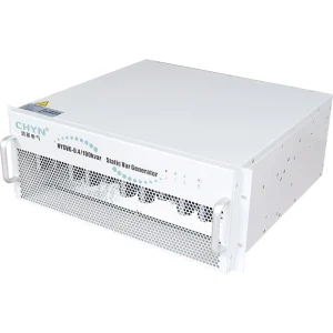
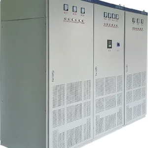
Electronic compensation may be considered where the documented duty and network arrangement support it. Ask which components of the current the proposed configuration addresses, how its capacity is allocated and what happens when it reaches a limit. Confirm neutral-path capability separately when that function is required.
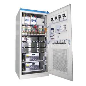
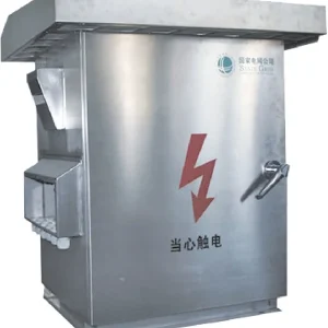
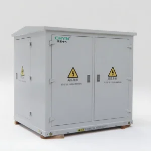
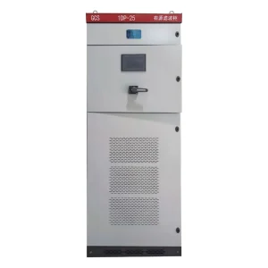
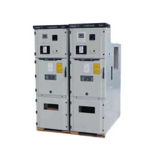
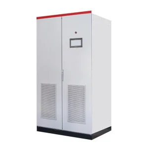
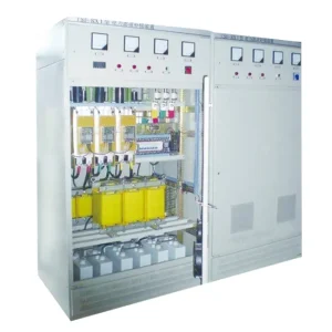
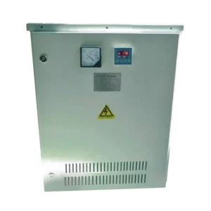
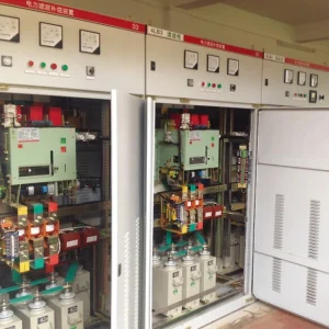
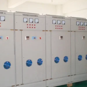
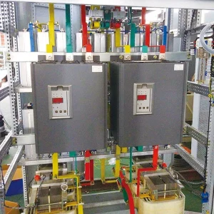
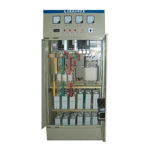
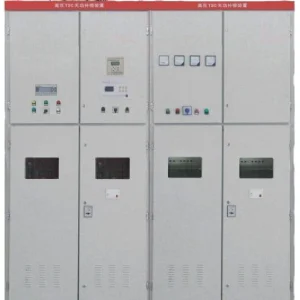
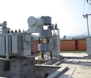
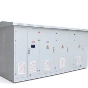
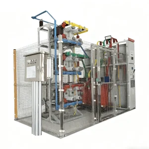
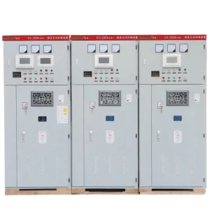
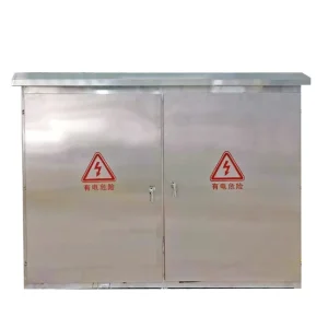
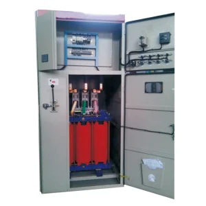
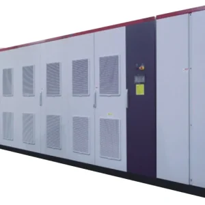
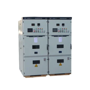
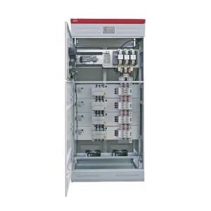
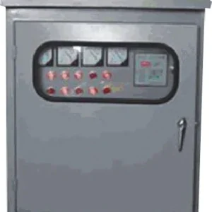
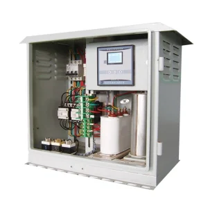
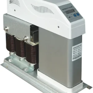
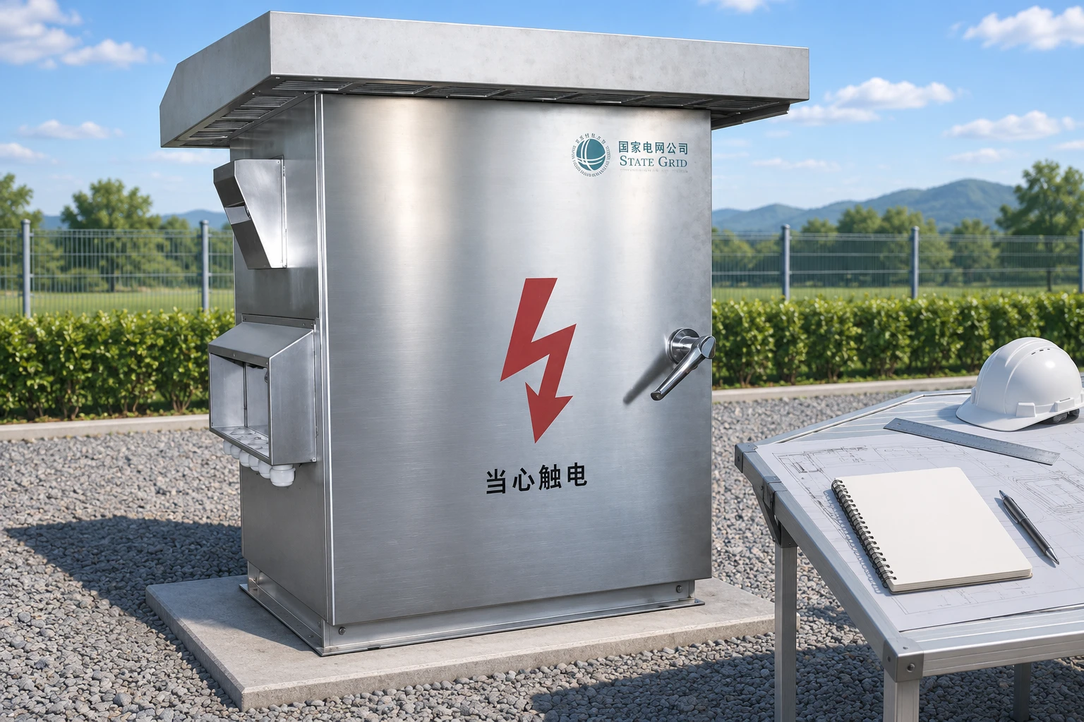
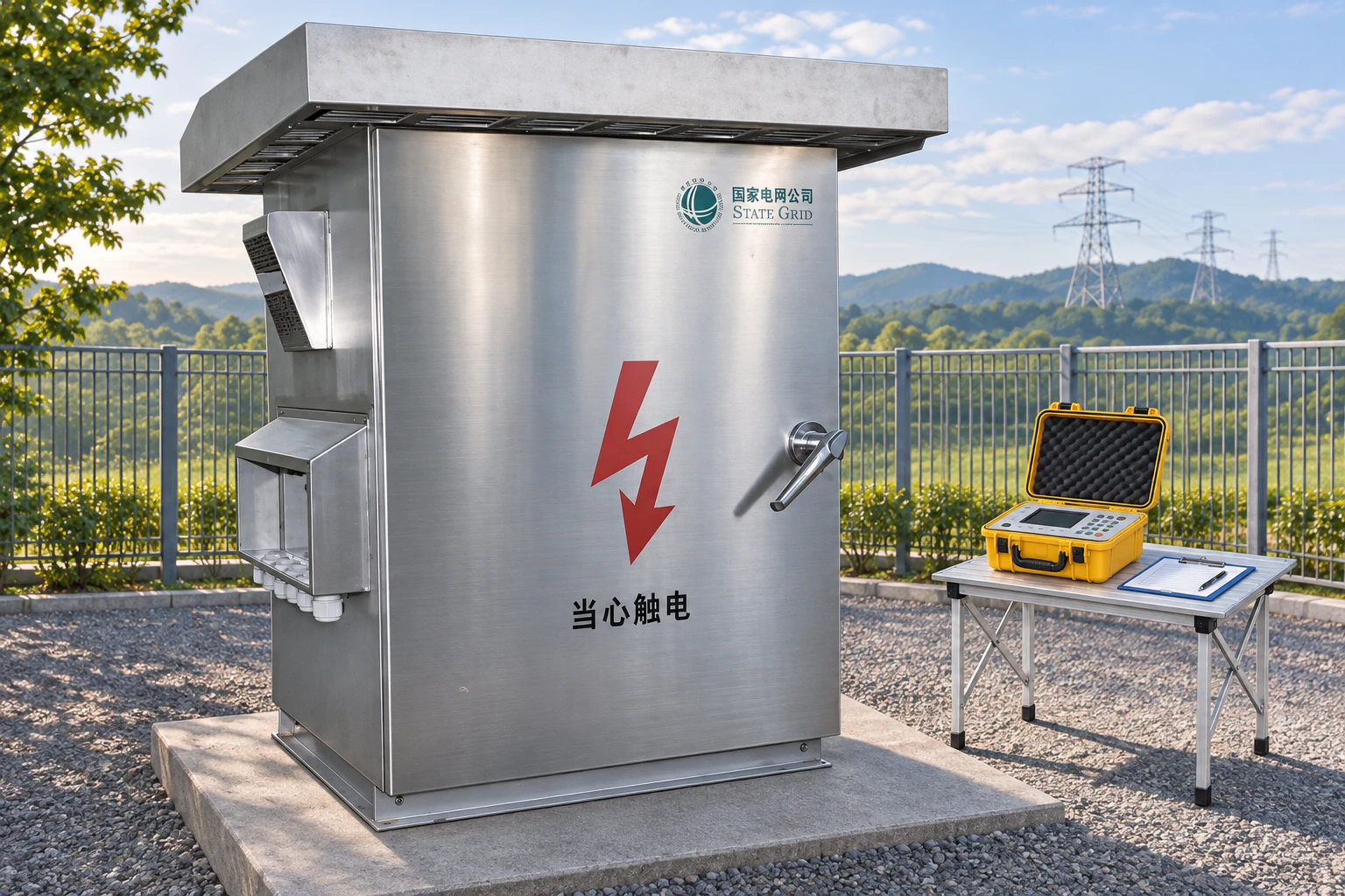
CHYN’s outdoor three-phase imbalance compensation product page provides a starting point for a site-specific inquiry. Supply the network diagram and synchronized measurements. The product photograph illustrates the enclosure and does not establish a current rating, neutral capability or guaranteed improvement.
Define acceptance at the intended boundary
Write the objective as a measurable requirement at a named bus or feeder. State the metric, calculation method, operating envelope and recording period. Identify whether the project also requires reactive-power support, harmonic compensation or neutral-current reduction, and keep the evidence for each objective visible.
Record comparable baseline and compensated conditions. Include the phase load state so that a change in production is not credited to the compensator. If the acceptance procedure uses several load cases, report each one, including cases in which the device reaches its capability limit.
Ask for the priority behavior under combined duties. A single device may allocate available current among several functions. A quotation should explain those priorities for the actual model and configuration. Separate maximum ratings stated for individual functions do not demonstrate simultaneous maximum performance.
Prepare the supplier inquiry and handover
Provide transformer and feeder data, earthing arrangement, phase and neutral measurements, harmonic spectra, relevant load schedules and the desired measurement boundary. Include installation temperature, outdoor exposure, enclosure constraints and communication requirements. Identify unknown inputs so the proposal can state its assumptions.
At handover, retain the accepted measurement definition, equipment configuration, commissioning records and operating limits. Define how alarms and saturation events are reviewed. If the load mix changes materially, compare the new condition with the accepted operating envelope rather than assuming the original selection remains adequate indefinitely.
For broader context, CHYN’s load-balancing and power-quality overview addresses system planning. The third-harmonic neutral-current guide explains a complementary four-wire issue, while SVG versus active harmonic filter helps distinguish compensation objectives.
Educational video: symmetrical components
“PS86 Symmetrical Components” from Lectures in Electrical Engineering presents the analysis method through an academic lecture by Dr. Tirupathiraju Kanumuri of NIT Delhi. It supports interpretation of sequence quantities and does not replace project measurements or equipment selection.

Watch PS86 Symmetrical Components on YouTube.
Track performance as the load mix changes
Retain a phase-load schedule with the commissioning baseline. If single-phase equipment is added, removed or moved between phases, update that schedule and compare the resulting measurements with the accepted envelope. A system that was balanced during one production arrangement can behave differently after an ordinary operational change.
Assign responsibility for reviewing alarms and capability-limit records. Persistent saturation, a new imbalance pattern or an unexplained neutral-current increase should lead to a fresh measurement review. This turns the handover data into an operating reference instead of leaving the compensator’s original acceptance report as a document that is never consulted again.
Frequently asked questions
Are current imbalance and voltage unbalance the same measurement?
No. They describe different quantities and can use different calculation methods. Record the instrument definition, measurement location and operating state. A voltage-sequence ratio should not be labeled as a current-imbalance result or compared directly with an unrelated index.
Does balancing phase currents guarantee low neutral current?
No. Neutral current can contain fundamental imbalance and harmonic components. Measure its spectrum and confirm the network arrangement. The capability required to address neutral harmonic current must be reviewed separately from a general phase-balancing objective.
Should compensation be installed before checking connections?
No. Establish whether a defect, instrument configuration error or unsuitable load allocation is responsible. Correct an identified fault through the approved procedure. A compensator should be selected for a documented duty rather than used to conceal an unresolved defect.
How should combined compensation duties be specified?
List each objective, the required measurement boundary and the expected operating envelope. Ask the supplier how available capability is allocated when duties occur together, including priorities and limits. Individual function ratings do not demonstrate simultaneous maximum performance.