
 Zhejiang Hongyan Electric Co., Ltd.
Active harmonic filter sizing starts with the amperes that must be compensated at a defined measurement point, across the plant's actual operating cases. Transformer capacity and a single THDi percentage do not establish that duty. Calculate the required harmonic current, decide whether reactive compensation or phase balancing must share the converter, then check the offered unit's continuous capability under the specified voltage and environmental conditions. A useful purchase specification states both the operating envelope and the residual distortion target. It also explains what happens when demand exceeds capacity, so a nominal current rating does not become an unsupported promise of complete harmonic removal.
Define the boundary before collecting numbers
Begin with a single-line diagram. Mark the injection point, current transformers, nonlinear feeders, capacitor branches and possible sources. An upstream measurement can include machines outside the proposed filter's control boundary. A measurement on one drive feeder can omit other loads that will later connect to the same bus. Neither measurement is inherently wrong; the error is using it to size equipment intended for a different boundary.
For a practical introduction to the compensation mechanism, see how an active harmonic filter works. This sizing discussion assumes a shunt current-injection device, not a series voltage conditioner. Improving a bus-voltage waveform and reducing a customer's harmonic-current contribution are related objectives, but they are not interchangeable acceptance tests.
Write the required result in measurable terms. Specify the evaluation location, operating cases, relevant harmonic orders, measurement method and reporting period. If a utility requirement applies at the point of common coupling, keep that boundary visible throughout the design. Do not move the acceptance measurement to a convenient downstream panel simply because the local result looks better.
Measure operating cases instead of chasing the highest percentage
Record fundamental current, total RMS current, individual harmonic currents, bus voltage and the associated process state on every phase. Capture production peaks, normal operation, reduced production and relevant source changes. A repeating process may require event records rather than a single long average. Preserve the time stamps so that electrical measurements can be matched to which machines were operating.
Current distortion is a ratio. A small fundamental current can produce a high THDi reading while requiring relatively little compensation current. A lower distortion percentage during full production can represent a larger ampere demand. Therefore, compare calculated current requirements across operating cases, rather than selecting the largest percentage from the analyzer screen.
Also distinguish fundamental current from total RMS current. When THDi is defined relative to the fundamental, harmonic current is Ih = I1 × THDi, with THDi expressed as a decimal. If only total RMS current is available, and the relevant components follow that definition, use I1 = IRMS / √(1 + THDi²). Check the analyzer's definitions and bandwidth before applying either expression.
Calculate the harmonic-only current requirement
For distinct measured harmonic orders in one phase, their combined RMS current is √(I2² + I3² + … + In²). This is a root-sum-square calculation, not an arithmetic sum. Include only the orders within the measurement and compensation scope. DC components, interharmonics and high-frequency emissions require separate consideration; a conventional harmonic rating does not automatically cover them.
As an illustrative arithmetic example, assume a phase carries 400 A of fundamental current and has 30% THDi. The combined harmonic current is 400 × 0.30 = 120 A. Under the same assumptions, total RMS current is approximately √(400² + 120²) = 417.6 A. Multiplying 417.6 A by 30% would overstate the harmonic current because the percentage uses the fundamental as its denominator.
Suppose a second operating case has 180 A fundamental current and 50% THDi. Its harmonic current is 90 A, below the first case despite the higher percentage. These are invented teaching inputs, not CHYN product ratings or plant measurements. They show why the survey needs simultaneous current and distortion readings. The eventual design must use measured or explicitly modeled project data.
If partial compensation is acceptable, specify residual current by order and operating case. A single target percentage cannot always be subtracted from the initial percentage to obtain a reliable filter size. Fundamental current may change, background distortion may remain and the controller may allocate current selectively. Ask the supplier to identify the assumptions behind any reduced-capacity proposal.
Reserve capacity for the duties that occur together
Harmonic filtering, fundamental reactive-current compensation and phase balancing can compete for converter capacity when those functions are supported. The ABS guidance on electrical harmonics discusses active-filter functions and the allocation of rated capacity between harmonic and reactive compensation. Its marine context should not be mistaken for a universal industrial acceptance standard.
Request a simultaneous-duty calculation from the supplier. It should state the controller's priority, per-phase limits and the residual performance at saturation. A harmonic-first arrangement can leave reactive demand uncompensated when fully loaded. A reactive-first arrangement can leave more harmonic current in the supply. Neither behavior should be discovered only after commissioning.
| Design input | What to record | Effect on the capacity decision |
|---|---|---|
| Harmonic spectrum | Amperes by phase and order for each operating case | Establishes the current to remove within the supported frequency range |
| Reactive duty | Fundamental reactive current occurring at the same time | Requires documented sharing or a separate compensation device |
| Neutral duty | Neutral current and its harmonic composition | Requires a suitable topology and explicit neutral-path capability |
| Environment | Ambient temperature, altitude and enclosure arrangement | Checks available continuous current after applicable derating |
| Expansion | Named future loads and their operating combinations | Supports a traceable reserve rather than an arbitrary percentage |
This table is a project planning checklist, not a standardized sizing table. For the system-conductor decision, use the separate guide to three-wire versus four-wire active filters. Do not infer neutral capability from the total phase-current rating.
Check frequency and installation limits
Two filters with equal headline amperes may differ in supported harmonic orders, control bandwidth and achievable output at higher frequencies. The research paper Analysis, Dimensioning and Robust Control of Shunt Active Filter treats dimensioning together with converter and control constraints. It supports reviewing more than a current nameplate; it does not certify the performance of a commercial cabinet.
Ask for the offered configuration's performance envelope at the actual voltage and frequency. Include the coupling arrangement, connection cable requirements, CT characteristics and source conditions. A cabinet with insufficient cooling or an unsuitable sensing arrangement will not become a satisfactory solution merely because its arithmetic current rating exceeds the preliminary requirement.
When several modules operate in parallel, obtain the approved coordination method, CT arrangement and expansion limits. Clarify whether a failed module reduces capacity smoothly or disables the group. If production must continue with one module unavailable, evaluate that operating case explicitly. Installed spare capacity and an operational redundancy requirement are different purchasing decisions.
Build a selection sheet that can be checked later
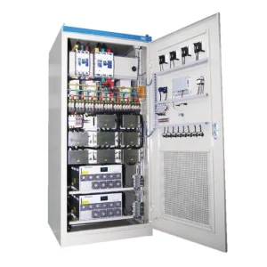
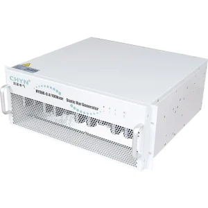
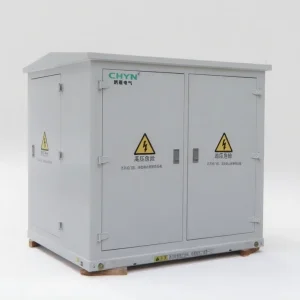
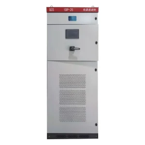
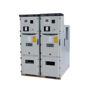
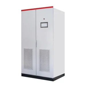
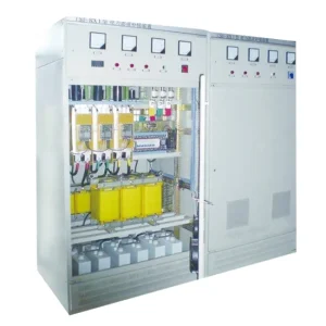
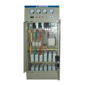
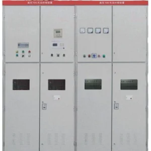
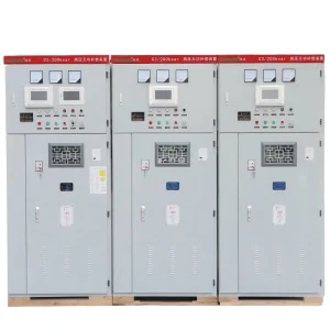
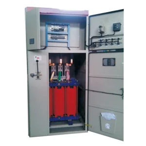
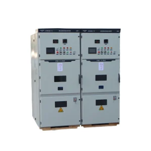
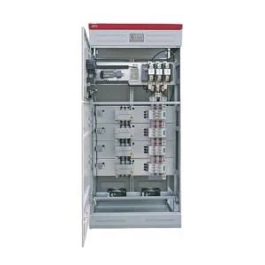
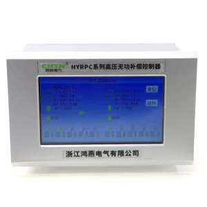
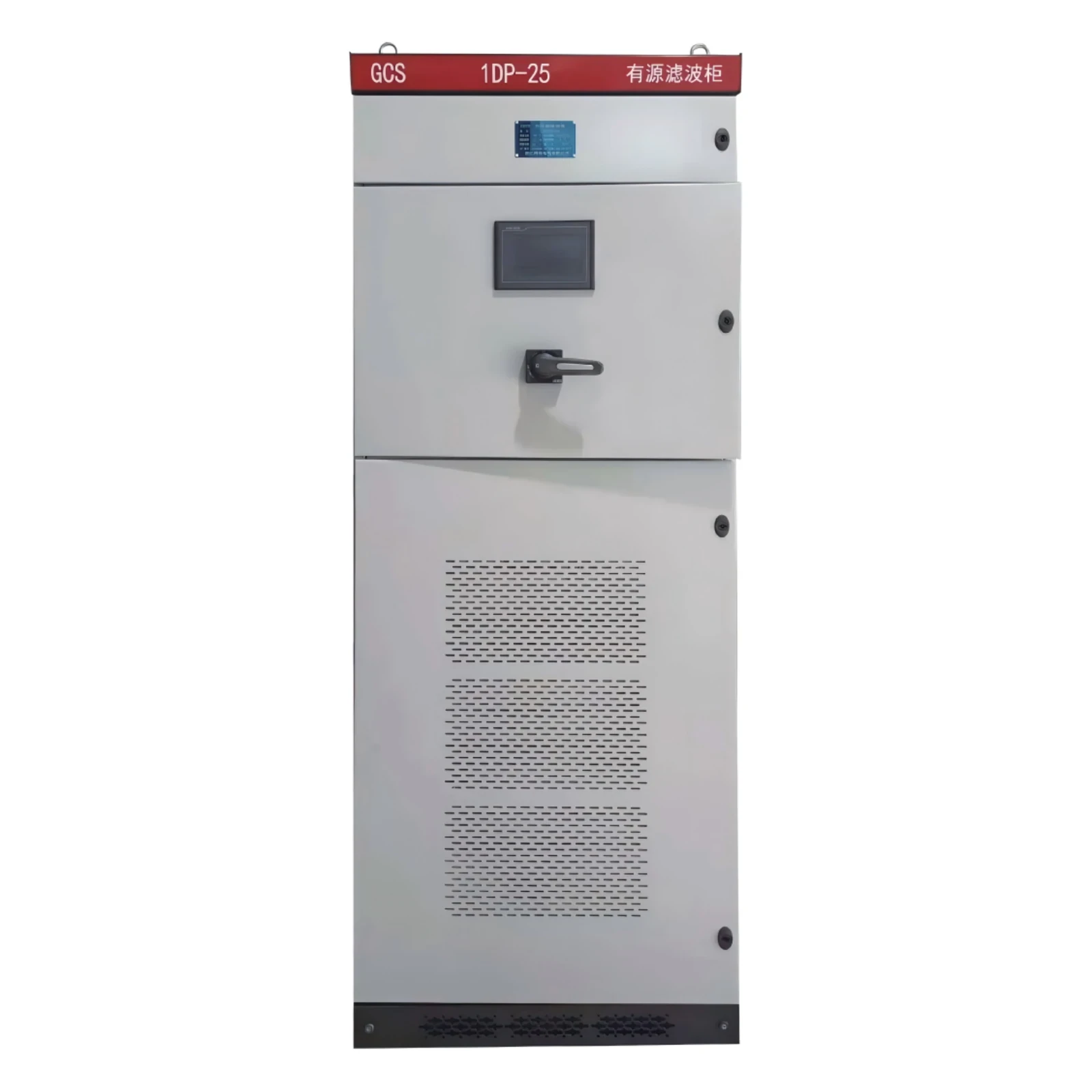
For the CHYN HYAPF active power filter, submit the survey, single-line diagram and required operating cases before requesting a configuration. The product photograph identifies the website's equipment family. It does not establish the current rating, conductor arrangement or compensation priorities of a particular offer.
The selection sheet should connect every capacity allowance to a reason. Separate measured present demand, credible growth, environmental reduction and any required operation with a module unavailable. Avoid stacking several unexplained margins, which can conceal uncertainty without addressing the real limiting operating case. A supplier should be able to reproduce the calculation from the stated inputs.
Include generator supply if it is part of normal or emergency operation. Different source impedance and existing capacitors can change system behavior. The related discussion of active filters on generator supplies explains why a utility-fed survey alone is insufficient for that case.
Verify the result with matched before-and-after measurements
Agree on the commissioning procedure before ordering. Use the same measurement boundary, instrument definitions and comparable load states for baseline and compensated records. Report fundamental current, harmonic spectrum, THDi, relevant demand-based metrics and voltage distortion together. A favorable percentage at a lightly loaded instant cannot establish performance throughout the specified production envelope.
Record filter output, current-limit flags, module availability and controller priorities during each test. A residual harmonic problem can come from insufficient capacity, an unsupported frequency, an incorrect measurement boundary or background distortion. These require different remedies. Increasing the cabinet size without checking the cause can leave the original problem unresolved.
Keep the final settings, CT ratios, firmware identification and test records with the accepted calculation. When a new production line is added, compare its measured contribution with the reserved capacity instead of assuming the old result still applies. The useful deliverable is a repeatable capacity decision tied to a known electrical system.
Further learning: current injection and compensation
This NPTEL lecture explains shunt active-filter operation. Use it to understand the compensation principle; project measurements and the offered equipment documentation remain the basis for sizing.
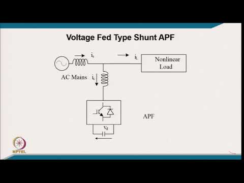
Watch the NPTEL lecture on YouTube.
Frequently asked questions
Can transformer kVA determine active harmonic filter size?
No. Transformer capacity describes the supply, while filter current depends on the measured compensation duty at the defined boundary. Use the harmonic spectrum and operating cases to establish that duty.
Is the highest THDi reading the worst sizing case?
Not necessarily. THDi is relative to fundamental current. A lower percentage at a higher fundamental current can require more compensation amperes.
Should harmonic and reactive current simply be added?
Obtain the supplier's simultaneous-duty calculation and priority rules. Different components occupy converter capacity differently, and per-phase or neutral limits may also govern.
Does extra current capacity guarantee a distortion target?
No. The measurement boundary, harmonic orders, source conditions, sensing and control limits also matter. Agree on a repeatable acceptance test at representative loads.