
 Zhejiang Hongyan Electric Co., Ltd.
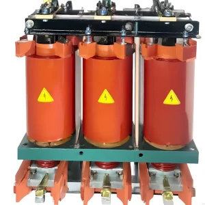
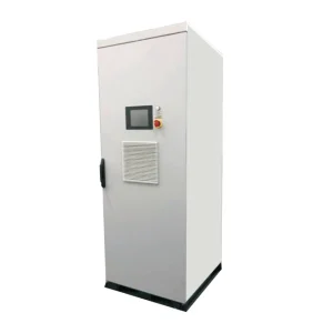
Static var generator sizing should cover the largest required capacitive and inductive compensation duties across credible operating cases, at the voltage where the equipment must deliver them. Begin with signed active and reactive power measurements, define the target at the agreed connection point, and calculate the compensation needed for each case. Then check converter current, environmental derating and any shared functions. One average power-factor reading cannot establish all of these requirements. The output should be a documented operating envelope with a suitable offered configuration, rather than a kvar number calculated without reference to load variation or the existing compensation equipment.
Define the controlled point and the desired result
Mark the SVG connection and measurement points on the single-line diagram. Identify the loads, transformer, capacitor banks, generation and bus ties inside the control boundary. The power factor at a machine terminal can differ from the value at the utility meter. If the purchase objective concerns the latter, calculate and verify the result at that boundary.
Decide whether the principal objective is displacement power factor, reactive-power exchange or bus-voltage support. They can overlap, but they require different studies and acceptance records. A power-factor correction calculation does not establish flicker performance or prove that a weak bus will remain inside a particular voltage envelope during a disturbance.
The parent explanation of what a static var generator does introduces the equipment. Here the focus is the continuous and changing reactive duty needed for selection. Product-specific response, overload and harmonic functions must be confirmed in the offered configuration rather than assumed from the equipment category.
Use signed measurements and credible operating combinations
Collect simultaneous active power P, fundamental reactive power Q, voltage, current, displacement power factor and true power factor. Record which sign convention the meter uses. For this article, positive Q means an inductive demand at the chosen boundary, while negative Q means capacitive behavior. A commissioning sheet should translate that convention into the actual controller's terminology.
Include peak production, minimum production, shifts with different machines, capacitor switching states and relevant generation conditions. If solar generation reduces imported active power without removing the plant's reactive demand, the ratio seen by the utility meter can change substantially. A nighttime average cannot represent that daytime condition. Preserve records showing P and Q together rather than independent maxima from unrelated time periods.
Map the valid combinations instead of adding every nameplate maximum. Some loads cannot run together, while maintenance or bus-tie operation may create an unusual but credible combination. Explain those assumptions in the selection sheet. A supplier can assess uncertainty more usefully when each operating case has a clear electrical and process description.
Calculate the fundamental reactive correction
For balanced sinusoidal conditions with positive imported active power, a preliminary correction calculation is Qc = P × [tan(arccos(PF1)) − tan(arccos(PF2))]. P is in kW, Qc is in kvar and the power factors represent the fundamental displacement relationship. The expression assumes a consistent lagging-to-target convention. Export and leading conditions need signed treatment rather than blindly inserting unsigned power-factor values.
Consider illustrative inputs of 500 kW, an initial lagging displacement factor of 0.80 and a target lagging displacement factor of 0.98. Initial Q is 500 × 0.75 = 375 kvar. Target Q is approximately 500 × 0.2031 = 101.5 kvar. The required capacitive correction is therefore about 273.5 kvar. These values demonstrate the calculation only; they are not an equipment recommendation or a measurement from a CHYN project.
If the load remains at 375 kvar while active import falls, the same unsigned power-factor shortcut becomes less informative than the signed P/Q record. Calculate the target reactive exchange directly for each case and subtract the existing contribution within the control boundary. The SVG must be sized for the residual duty it actually controls, not for an outdated before-correction figure.
For distorted waveforms, true power factor includes effects that fundamental reactive compensation alone may not remove. See the related distinction between an SVG and an active harmonic filter. Do not promise a true-power-factor result from the displacement formula without checking the harmonic-current contribution and the functions of the offered unit.
Size both capacitive and inductive directions
A plant that needs capacitive support at full production may need inductive absorption at low load when fixed capacitors remain connected. Treat those as separate ends of the required operating range. The offered equipment's continuous capability should cover both where needed, with its sign conventions and any asymmetry clearly documented.
The original simulation study Compensation of Reactive Power in Grid-Connected Solar PV Array System Using STATCOM and Fixed Capacitor Bank examines changing generation and load conditions with fixed and dynamic compensation. Its scenario-based results are useful background for considering operating variation; they are not a universal sizing rule or proof of CHYN performance.
| Operating case | Calculation focus | Selection evidence |
|---|---|---|
| High inductive load | Required capacitive injection after existing compensation | Continuous positive-duty capability at the specified voltage |
| Light load with fixed capacitors | Required inductive absorption or permitted capacitor disconnection | Negative-duty capability and agreed bank-control strategy |
| Low bus voltage | Current needed to deliver the required reactive power | Voltage-current capability envelope and operating limits |
| Source or bus-tie change | New measurement boundary and network behavior | Approved settings group and applicable system study |
| One module unavailable | Residual continuous capacity if redundancy is required | Defined production restriction or sufficient remaining modules |
The table identifies review questions rather than numerical design limits. If switching fixed banks can remove an excessive light-load capacitive condition, compare that strategy with purchasing additional inductive SVG capacity. The final choice depends on operational constraints, switching duty and the required dynamic behavior.
Translate kvar into current at the actual voltage
For balanced fundamental three-phase reactive duty, Iq = |Q| / (√3 × VLL). Using kvar and kV gives amperes. An illustrative 100 kvar at 0.4 kV requires approximately 144.3 A. At 0.36 kV, delivering the same 100 kvar requires approximately 160.4 A. This arithmetic explains why a kvar label at nominal voltage does not by itself establish low-voltage output.
For a fixed available current, reactive power varies with voltage through Q = √3 × VLL × Iq. Actual converters also have control, DC-link and protection limits, so this relationship is only part of the capability envelope. Obtain the supplier's allowed voltage range and continuous output curve instead of extrapolating operation to arbitrarily low voltage.
The German transmission operators' standardized E-STATCOM design requirements explicitly describe reactive capability in relation to voltage and current. Those transmission-scale requirements are not ratings for an industrial low-voltage SVG. They illustrate why a capability envelope is more informative than one nominal reactive-power number.
Account for shared duties, cooling and module availability
If a configuration also offers unbalance or harmonic compensation, ask how those functions share converter current with reactive compensation. Define which function has priority when the limit is reached. A proposal should identify the residual reactive capability under the simultaneous duty, rather than listing maximum values for several functions that cannot all be delivered together.
Confirm the environmental assumptions behind the continuous rating. Supply ambient temperature, altitude, enclosure ventilation and installation clearances. Request applicable derating data and assess the required duty against the reduced available output where relevant. Avoid inventing a generic derating percentage; the correct value depends on the supplied design and its documented operating conditions.
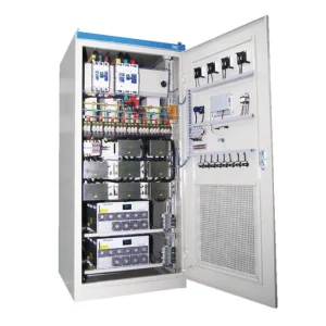
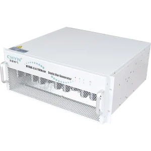
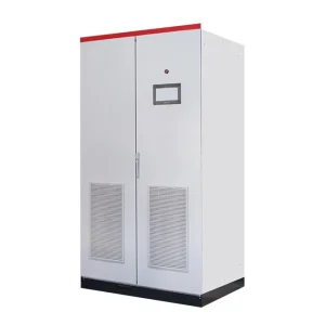
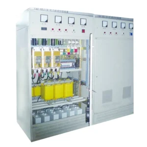
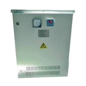
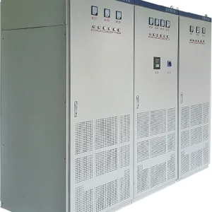
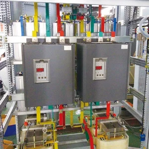
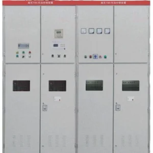
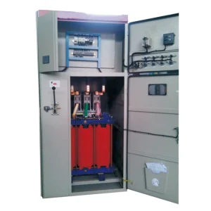
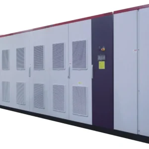
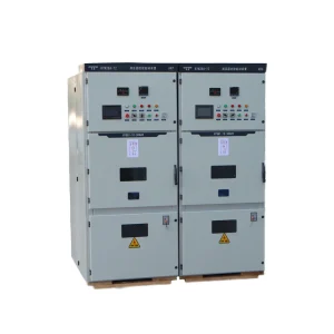
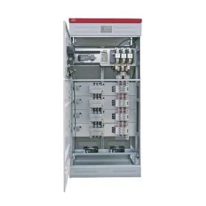
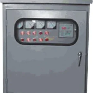
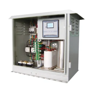
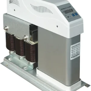
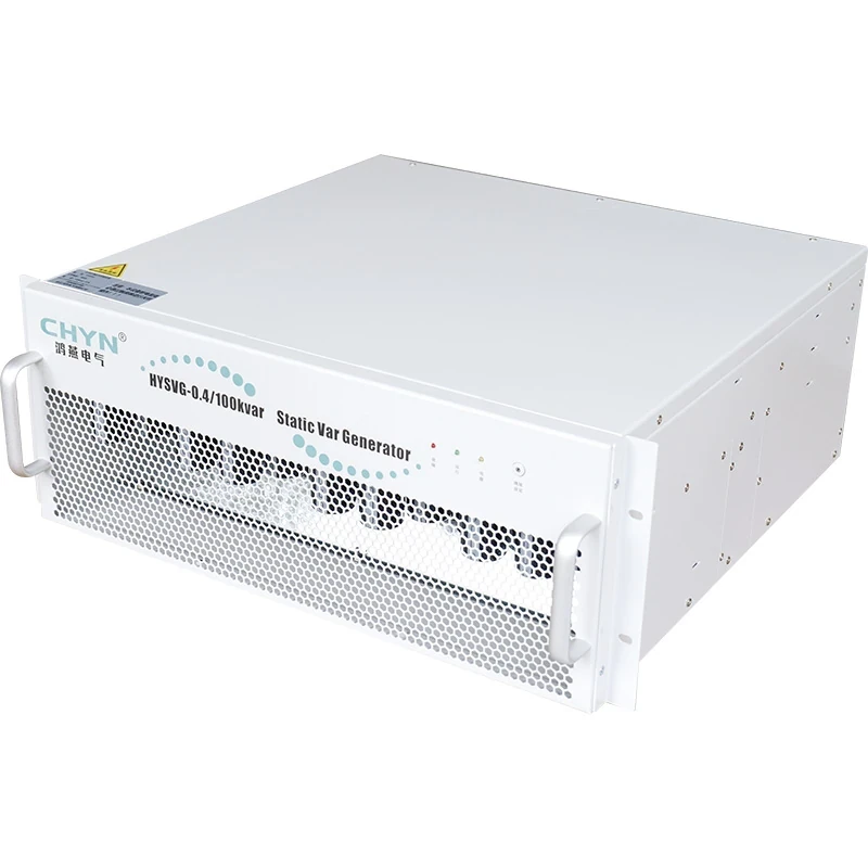
The CHYN HYSVG static var generator provides a relevant product family for this discussion. The original website image shows a module, not a complete engineered installation. Confirm module quantity, cabinet assembly, protection, connections and continuous bidirectional capability in the quotation before treating the selection as final.
Where the owner requests operation with one module unavailable, state the surviving duty explicitly. A spare module stored off-site is different from installed capacity that remains available during a failure. Include the intended production restrictions and repair assumptions in the commercial comparison so competing offers address the same service requirement.
Verify the selected operating envelope
Before commissioning, agree on the measurement point, instrument definitions, target reactive exchange and relevant operating cases. Check the measurement chain before increasing compensation output. The related guide to SVG CT polarity explains a common measurement issue that can undermine an otherwise correct capacity calculation.
Test both required directions where the approved procedure and plant conditions allow. Record P, Q, voltage, phase currents, output current, current-limit indications and the state of existing banks. Observe steady-state performance and transitions separately. A successful low-load test cannot demonstrate the maximum capacitive duty, and a full-production test may not demonstrate inductive absorption.
Keep the final calculation, capability curves and settings with the acceptance record. If a later process change alters P/Q behavior, revisit the operating cases. This makes static var generator sizing a maintainable engineering decision rather than a number detached from the conditions that justified it.
Further learning: the STATCOM model
This NPTEL lecture explains basic mathematical modeling of a STATCOM. It provides background for reactive-current control; the supplied SVG's documented limits govern an actual purchase.

Watch the NPTEL lecture on YouTube.
Frequently asked questions
Can one average power factor establish SVG capacity?
No. Use simultaneous signed active and reactive power across peak, minimum-load and other credible operating cases, including the states of existing compensation.
Does a kvar rating remain constant when voltage falls?
Not automatically. At fixed available reactive current, reactive power falls with terminal voltage. The actual converter capability also depends on its operating and protection limits.
Why might an SVG need inductive capacity?
Fixed capacitors or other capacitive sources may produce excessive capacitive behavior at light load. The design may require inductive absorption or an approved switching strategy.
Can an SVG always correct true power factor to the target?
Fundamental reactive compensation improves displacement power factor. Harmonic distortion can still limit true power factor, so the target must reflect the measured waveform and offered functions.