
 Zhejiang Hongyan Electric Co., Ltd.
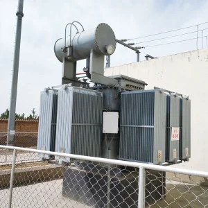
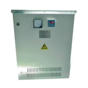
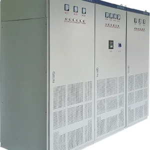
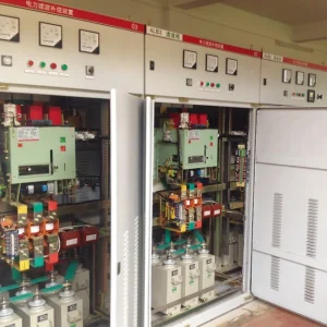
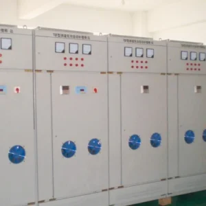
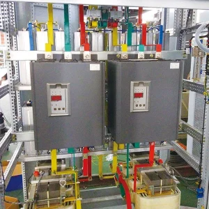
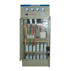
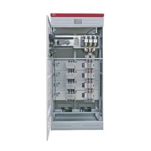
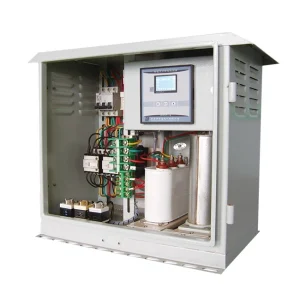
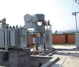
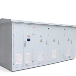
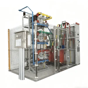
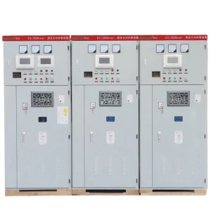
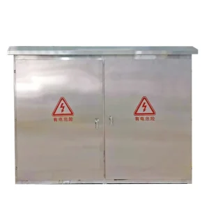
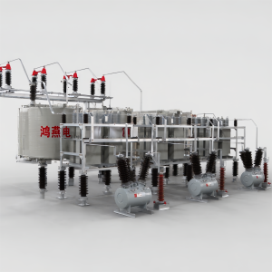
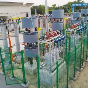
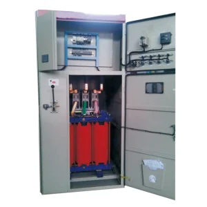
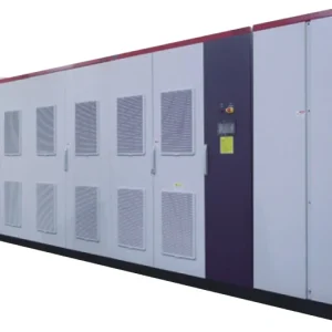
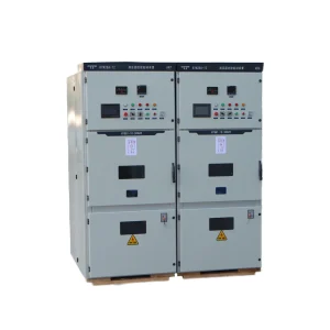
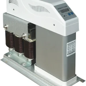
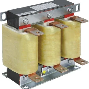
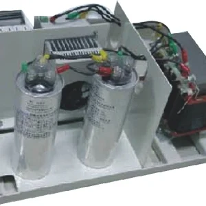
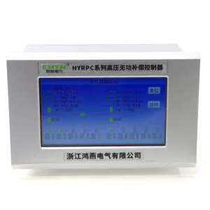
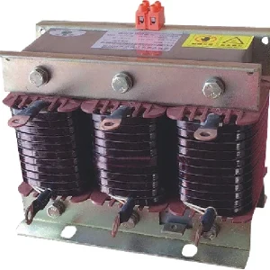
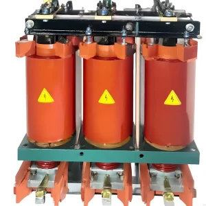
A static var generator undervoltage event needs two separate checks: how much reactive current remains available while the unit operates, and whether its protection has blocked compensation. A lower kvar reading during a voltage dip does not automatically mean an SVG has failed. At a fixed reactive current, available reactive power decreases with voltage; outside its approved operating envelope, the converter may reduce current or stop. Diagnose the event from synchronized bus voltage, SVG current, operating state and timestamps before changing settings or ordering additional capacity.
This guide focuses on investigating reduced output and undervoltage trips. It complements SVG capacity planning, rather than replacing the initial sizing study. Any continued operation during a disturbance must follow the supplied equipment's documented capability.
Distinguish an operating range from a support guarantee
An input-voltage range says where equipment is intended to operate under stated conditions. It does not, by itself, promise full nameplate kvar at every voltage, full output for every event duration, or uninterrupted service during an unbalanced fault. A procurement document should distinguish continuous operation, temporary operation, current capability and protective blocking. When those items are combined into one broad voltage statement, buyers cannot determine what support remains during a real disturbance.
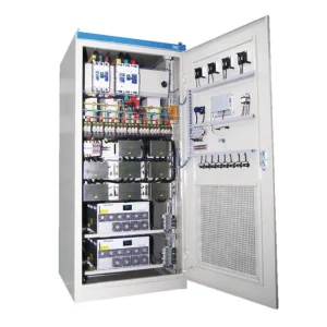
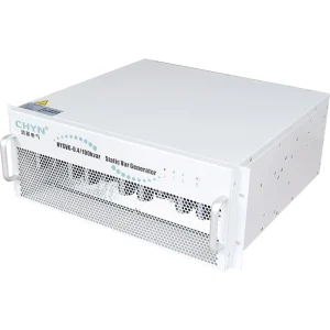
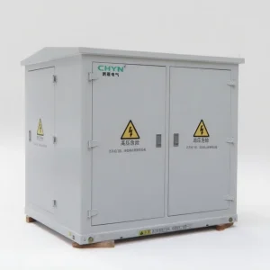
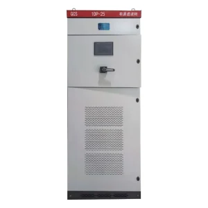
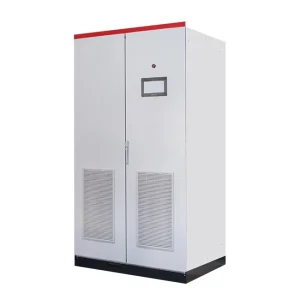
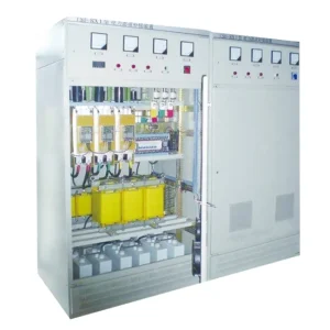
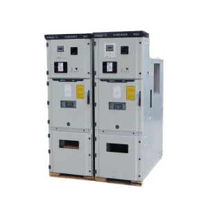
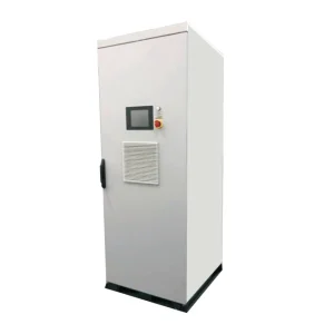
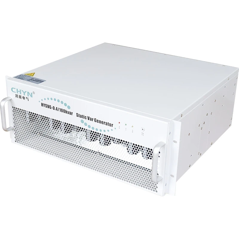
The CHYN HYSVG static var generator page lists reactive compensation, monitoring and undervoltage protection. These are reasons to request the project's detailed capability and protection records. They do not establish a tested ride-through curve for an unspecified configuration. Confirm the offered model, firmware, cooling arrangement and connection voltage before comparing its behavior with a specification.
ENTSO-E's STATCOM overview describes converter-based reactive-current support and its current limitation. It discusses transmission equipment; the general principle helps explain SVG behavior, but its response claims must not be transferred to a particular industrial module.
Use current and voltage together to interpret kvar
For a balanced, sinusoidal three-phase system with purely reactive fundamental current, the useful relationship is Q = √3 × VLL × Iq. Here Q is reactive power in var, VLL is line-to-line RMS voltage in volts, and Iq is fundamental reactive line current in amperes. Divide by 1,000 for kvar. Total RMS current cannot be substituted for reactive current when harmonic or active components are significant.
Consider a deliberately simplified example: a converter supplies 100 A of reactive current at 400 V. Its reactive output is approximately 69.3 kvar. At 320 V with the same reactive current, output is approximately 55.4 kvar. The 20% voltage reduction produces a 20% kvar reduction in this fixed-current example. It does not show that any named SVG can sustain 100 A at 320 V, and it does not predict the voltage improvement at a remote motor terminal.
The published research Technical comparison of FACTS controllers in parallel connection explains why STATCOM reactive output varies approximately with voltage at its current limit, while a fixed shunt capacitance follows a voltage-squared relationship. Both descriptions have operating boundaries. Neither establishes that compensation can continue down to zero voltage.
Classify the event before choosing a remedy
| Recorded condition | Question to resolve | Evidence to request |
|---|---|---|
| Lower kvar, similar reactive current, unit remains enabled | Does voltage explain the change? | Simultaneous fundamental voltage, reactive current and kvar |
| Current plateaus below the requested value | Which operating limit is active? | Current request, available-current indication and limit flags |
| Output stops with an undervoltage record | Did the event cross the approved protection boundary? | Per-phase voltage trace, event duration and exact trip settings |
| One phase behaves differently | Is this an unbalanced disturbance or measurement problem? | Phase-resolved waveforms, sensing configuration and phase labels |
| Output returns but bus voltage remains low | Is the cause outside the compensator's scope? | Source impedance, feeder loading and upstream event records |
This is a diagnostic decision table, not a set of universal trip limits. Its fixed-current interpretation follows the relationship above. The supplier's approved capability curve and the site's protection study establish acceptable voltage, current and time combinations.
Capture a common timeline across the installation
Start with the event record, not a photograph of one display after recovery. Record where voltage was measured, whether it was phase-to-phase or phase-to-neutral, which RMS window was used, and whether the data include minimum values. Obtain SVG state, demanded current, actual current and the first alarm. A later communications alarm may describe the consequence of a shutdown rather than its initiating cause.
Compare clocks between the power-quality recorder, SVG controller, feeder relay and production system. Note any known offset. If a motor start coincides with the event, identify the start request, contactor operation and acceleration interval. Without a shared timeline, a normal current reduction after a trip can be mistaken for the event that caused the trip.
Record other compensation equipment as well. A capacitor step opening, a parallel converter becoming unavailable, or a feeder transfer can change the reactive demand seen by the remaining SVG. Keep a drawing of the measurement boundary with the data. A bus meter and a downstream motor meter may both be correct while reporting different voltage dips.
Check the available-current envelope
Ask which restrictions applied at the event temperature and duration. A continuous current rating, a temporary overload allowance and an instantaneous protective ceiling serve different purposes. An overload available for one specified period must not become a continuous design assumption. Cooling restrictions and unavailable modules can also change the usable total.
For equipment offering several compensation functions, obtain the documented allocation of current between them. A demand for reactive compensation does not prove that all semiconductor current capacity is available for that function. Compare the enabled functions and priorities with the accepted configuration; do not assume that a feature listed on a general product page is enabled on the installed unit.
Existing parallel SVG arrangements need a further check: did all modules see the same event and remain permitted to operate? Review module-level records before treating the cabinet's total output as the capability of one healthy module. Confirm that the supervisory controller did not intentionally restrict recovery.
Investigate blocking and recovery separately
If compensation stopped, compare the measured event with the approved voltage-time boundary and the controller's measurement definition. Check whether the recorded limit applies to one phase, all phases or a calculated quantity. A positive-sequence voltage trace is useful for some studies, but it cannot automatically substitute for a minimum phase-voltage protection input.
Do not lower undervoltage protection merely to keep the display active. Request a manufacturer assessment if the installation needs support beyond the documented envelope. The review may involve synchronization, control-power continuity, converter voltage headroom and protective coordination. Each belongs to the actual hardware and application rather than a generic SVG setting.
After voltage returns, check the specified recovery sequence and the reason for any continued inhibition. Establish whether operator acknowledgement, a stable-voltage period or another interlock is required. Record the first restored current and the resulting bus condition. Repeated resets without understanding the cause can erase useful evidence and expose equipment to repeated unsuccessful operation.
Decide whether reactive support addresses the underlying problem
A shunt compensator changes reactive current at its connection point. It does not create an unlimited voltage source for the whole plant. The outcome depends on network impedance, the disturbance location and the remaining connected load. A deep upstream fault or an interruption requires a different assessment from a moderate voltage drop associated with a local load change.
Use the measured event to define the production requirement: which load must stay operational, at which terminal voltage, for how long? Compare that requirement with the verified support study. If the problem concerns sensitive equipment riding through a sag, coordinate the investigation with the plant's voltage-disturbance strategy rather than assuming that more kvar alone will solve it.
Also distinguish an undervoltage event from ordinary low-demand behavior. The checks for SVG operation at light load address leading or residual reactive demand under otherwise normal supply conditions. A dip investigation instead needs event timing, voltage boundaries and recovery evidence.
Prepare a useful technical inquiry
Send the supplier the single-line diagram, exact model identification, event waveforms, settings revision and operating-state log. Include simultaneous values rather than unrelated daily averages. State the desired reactive current and the required voltage-time profile, with the measurement point clearly identified. Ask for separate continuous, temporary and blocked regions on the proposed capability description.
For acceptance, agree in advance which checks are analytical, which use an approved test source, and which can be witnessed through recorded site events. Deliberately creating a plant undervoltage is not a routine troubleshooting action. The responsible engineer must approve any test that changes the live supply, its isolation arrangements and the affected production loads.
The closeout record should connect one observed symptom to one verified explanation: expected kvar reduction at available current, a documented limit, a correctly initiated protection action, or a fault requiring repair. Keep the original event and the post-correction record together so the next investigation begins with evidence rather than a repeated guess.
Further learning: how the converter model works
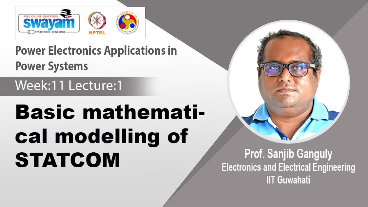
This NPTEL IIT Guwahati lecture introduces STATCOM mathematical modeling. It provides background for voltage and reactive-current relationships; it is not a demonstration of CHYN undervoltage performance or a replacement for the supplied capability curve.
Watch the educational lecture on YouTube.
Frequently asked questions
Does lower kvar during a voltage dip prove the SVG is faulty?
No. Compare reactive current and voltage at the same instant. Reactive power falls with voltage at fixed reactive current, while protection or other operating limits may reduce it further.
Does the input-voltage range guarantee full output?
No. Obtain the model-specific current capability, duration limits and blocking boundary. An operating range alone does not define the entire voltage-time performance envelope.
Should undervoltage protection be disabled to maintain compensation?
No. Preserve approved protection and investigate the initiating event. Any revised capability or setting requires an application review by the responsible engineer and equipment manufacturer.
What is the most useful first record?
A synchronized record of phase-resolved voltage, SVG current and operating state, accompanied by event timing, settings and the measurement-point drawing, is more useful than a single post-event kvar value.