
 Zhejiang Hongyan Electric Co., Ltd.
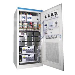
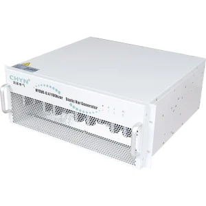
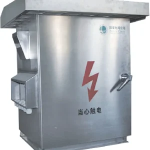
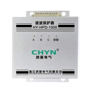
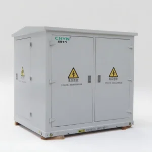
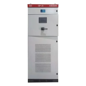
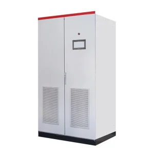
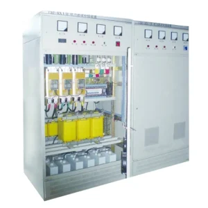
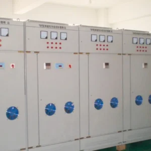
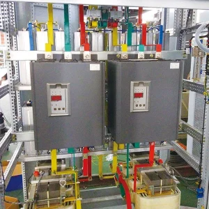
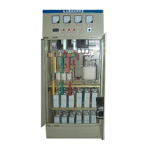
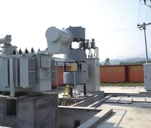
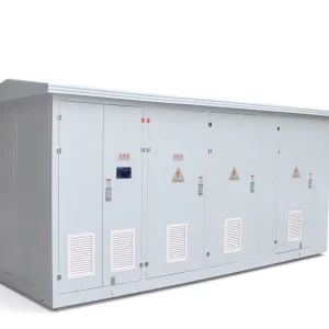
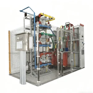
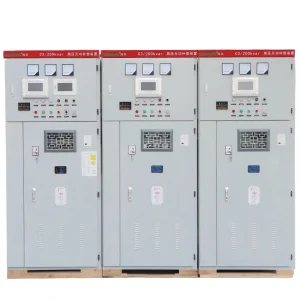
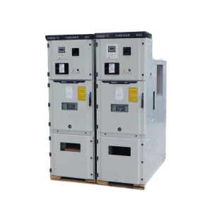
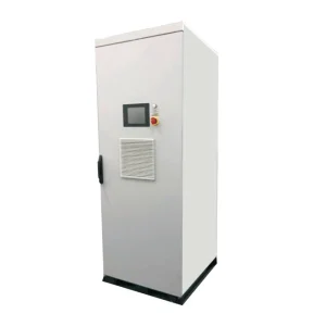
Active harmonic filter low load THDi can remain high even when the filter has substantially reduced harmonic current in amperes. Before rejecting performance, compare the fundamental current, residual harmonic amperes, measurement location and operating state. A percentage without its denominator cannot show how much unwanted current remains. The acceptance decision also needs the agreed measurement method and applicable site requirements. This article explains a practical low-load verification workflow; it does not assign a universal THDi target or claim a guaranteed CHYN result at any load level.
Separate a small denominator from a real compensation problem
Consider a plant where the night shift runs only controls, lighting and a few variable-speed drives. The daytime filter commissioning report looks satisfactory, but the night-shift analyzer displays a larger current-distortion percentage. That change deserves investigation, although it does not establish that the filter has failed. A smaller fundamental component can make the remaining harmonic current look larger when expressed as a percentage.
Use a hypothetical comparison with fundamental-referenced THDi. At one operating point, a fundamental current of 100 A and a combined harmonic current of 10 A give 10% THDi. At another point, 10 A fundamental and 3 A harmonic give 30% THDi. The second percentage is higher while the harmonic amperes are lower. These figures illustrate arithmetic only: neither operating point is a product test, an acceptance limit or a sizing recommendation.
The general harmonic-to-fundamental relationship is described in NI's measurement reference on total harmonic distortion. That reference discusses signal measurement rather than AHF acceptance. Here the same RMS ratio is applied to current components: THDi = 100 × Ih / I1, where I1 is fundamental RMS current and Ih is the root-sum-square of the included harmonic RMS currents. Confirm which harmonic orders and denominator your instrument actually uses.
For the broader operating principle, review how an active harmonic filter works. This article concentrates on interpreting and accepting its low-load measurements.
Build a comparable low-load test record
Start by naming the measurement point on the single-line diagram. Source-side current downstream of the utility connection, a particular load feeder and the filter output answer different questions. If the filter's sensors and the independent analyzer observe different boundaries, their displayed values may legitimately differ. Mark every probe location and current direction before comparing reports.
Record which machines are operating, their production states, connected capacitor steps, generator status and filter operating mode. Keep these states as comparable as practicable when collecting approved filter-enabled and filter-disabled measurements. Do not interrupt production or bypass protection just to create a comparison. If changing states is prohibited, use authorized historical records or a planned commissioning window and identify the limitation explicitly.
| Record item | Why it matters at low load | Evidence to retain |
|---|---|---|
| Fundamental current per phase | Defines the THDi denominator | Time-aligned I1 values and operating state |
| Individual harmonic amperes | Shows which components actually remain | Order-by-order spectrum with units |
| Voltage distortion | Distinguishes current improvement from the voltage condition | Same-point voltage spectrum and RMS trace |
| Filter mode and alarms | Reveals whether compensation was enabled or limited | Timestamped controller log and settings export |
| Analyzer configuration | Prevents incompatible comparisons | Probe range, ratio, bandwidth and aggregation settings |
This table is an engineering record checklist, not a statement of mandatory limits. Set the required recording period and statistical treatment in the project acceptance plan. A brief screenshot can explain a momentary symptom; it cannot establish behavior throughout an operating cycle.
Check the instrument before changing the filter
A current probe selected for maximum plant demand may operate close to the bottom of its useful range during a light-load test. Review the instrument and probe accuracy specifications at the actual measured current, together with bandwidth and phase performance. A quoted accuracy at a favorable range does not automatically apply to a much smaller signal. Choose suitable approved equipment and have a qualified person make any connection changes.
Confirm the analyzer's CT ratio, wiring configuration and channel assignment. Inspect exported data rather than relying entirely on the front-panel percentage. For example, a report labeled THD may use a different denominator or include a different frequency range from the quantity promised in the purchase specification. THD plus noise is another measurement and should not silently replace harmonic-only THDi.
For a scaling investigation, use the separate guide to matching the AHF CT ratio and controller scaling. The present workflow assumes that sensor selection and wiring have already been verified. Repeating a capacity calculation will not correct a measurement chain that reports the wrong current.
Look for operating-state limits in the controller record
Ask whether the selected filter supports a documented low-current threshold, standby mode or other operating condition that changes its compensation behavior. Obtain the answer for the supplied hardware and firmware. Do not infer the existence, value or adjustability of such a function from another manufacturer's manual or a generic AHF description.
Read the actual enabled functions as well. Harmonic compensation, reactive-current correction and load balancing may have separate commands or priorities. If the unit assigns its available output among several functions, the acceptance record should show that allocation. A low-load investigation should identify the current request, delivered current and any active limit together, rather than assuming a percentage target controls every operating state.
When logs indicate a current ceiling or competing demands, continue with AHF current limiting and compensation priorities. That is a different failure path from a rising ratio caused mainly by a falling denominator. Treating them separately makes the corrective action easier to verify.
Distinguish local improvement from site compliance
A successful feeder comparison can support a filter performance claim for that feeder and test condition. It does not automatically demonstrate compliance at the utility interface. Conversely, a percentage measured at a lightly loaded machine should not be assigned the acceptance limits for a different measurement boundary without reviewing the applicable requirements.
The FAA's Power System Studies order explains, within its facility-study context, that IEEE 519 harmonic limits apply at the point of common coupling rather than individual equipment or arbitrary internal locations. Use the current standard, utility requirements and project agreement for your own installation. This reference is not a substitute for those documents and does not establish a universal AHF output limit.
Keep a contractually required low-load THDi target visible even if the denominator explains a high percentage. An explanation of the ratio does not waive the specification. If the target cannot be verified within the agreed measurement uncertainty, document the uncertainty and resolve the test method with the responsible parties before declaring either compliance or failure.
Use residual amperes to decide the next investigation
If the harmonic amperes fall while THDi rises, inspect the denominator and test conditions first. If particular harmonic currents increase, compare voltage distortion, load spectrum and controller state. If the filter is disabled, alarmed or running an unexpected mode, resolve that condition before making a broad judgment about its hardware capability.
Keep phase results separate. A three-phase average can hide a lightly loaded phase with a high ratio or a phase where a particular harmonic remains. In a four-wire system, neutral current is another relevant record; do not assume a phase-current improvement proves that the neutral conductor condition is satisfactory. Confirm the supplied filter topology and supported functions before asking it to correct a particular component.
Escalate with evidence that allows the supplier to reproduce the question: the single-line diagram, time-aligned waveforms, spectra, current ratios, firmware details and alarm history. State the question in amperes as well as percentages. A request such as “explain why the seventh-harmonic source current remains at the recorded level in this operating state” is more actionable than a photograph of an unexplained red THDi number.
Prepare an acceptance and purchasing checklist
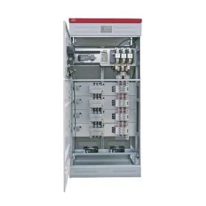
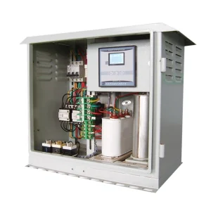
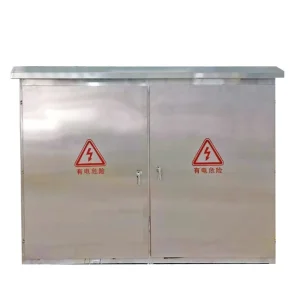
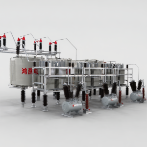
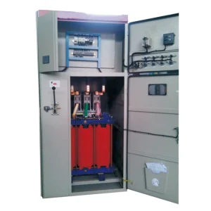
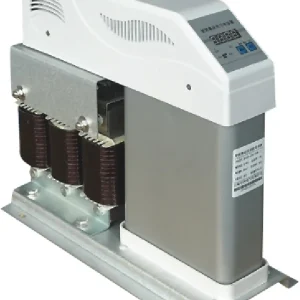
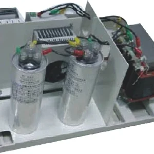
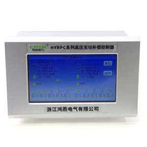
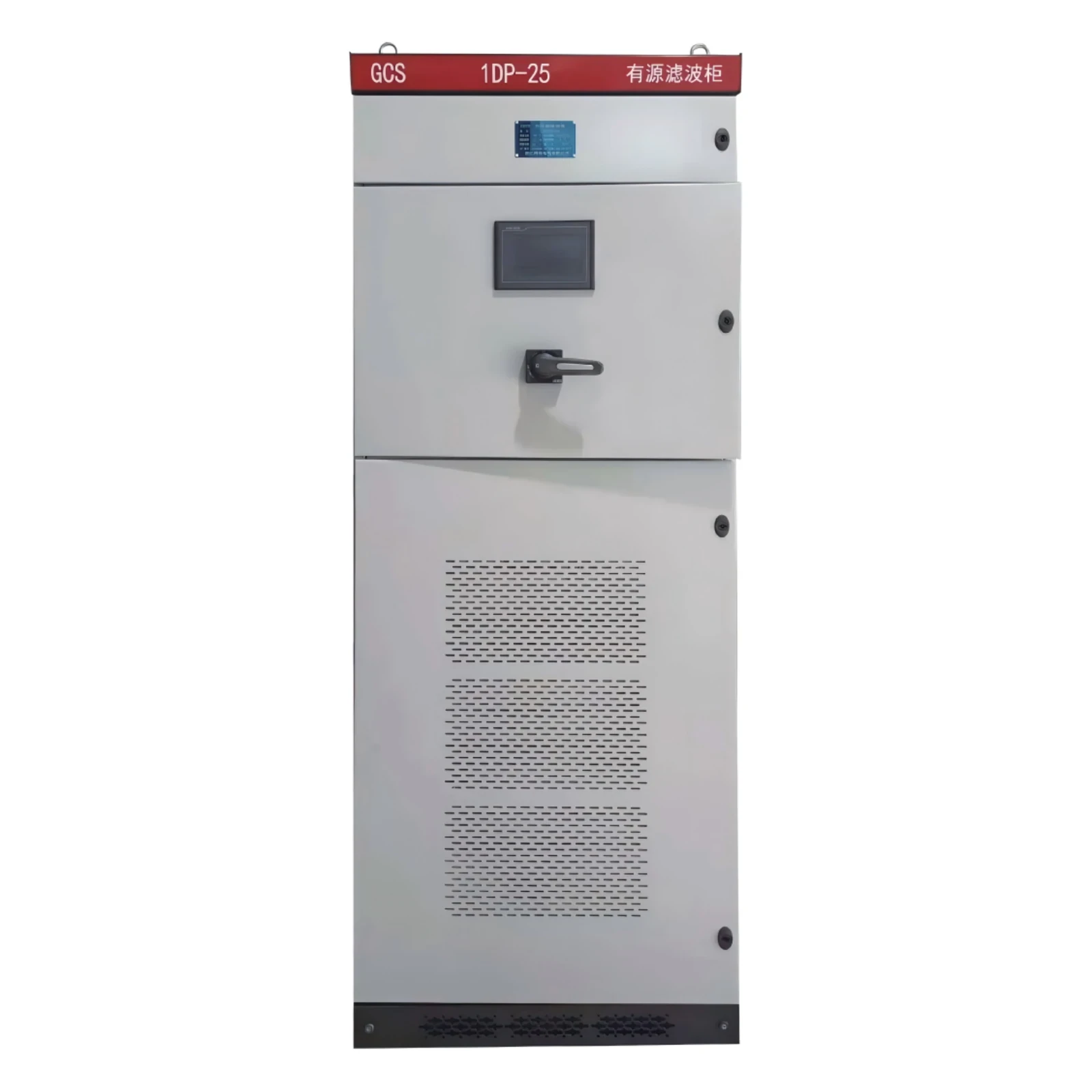
For an enquiry about the CHYN HYAPF active power filter, provide the minimum and maximum operating states, system voltage and frequency, three-wire or four-wire connection, measured spectra and installation boundary. Request a written statement of supported operating modes and the performance evidence applicable to the proposed configuration.
Define separate deliverables for commissioning, routine monitoring and troubleshooting. Commissioning needs the agreed test states and acceptance criteria; routine monitoring needs repeatable trend quantities; troubleshooting needs higher-detail event records. Saving these under one site naming scheme makes later comparisons possible without guessing which probe, feeder or production shift a file represents.
Include a clear disposition for each outcome: accepted, correction required, or inconclusive because a stated test condition was unavailable. Preserve the raw data along with the signed report. This avoids turning a conditional result into a blanket product guarantee when the plant later adds loads or changes its supply arrangement.
Educational video: understand the power-quality measurement context
The NPTEL lecture below introduces distribution-system power-quality problems. It supports the measurement context and terminology, rather than demonstrating a low-load CHYN test or providing a contractual harmonic limit.
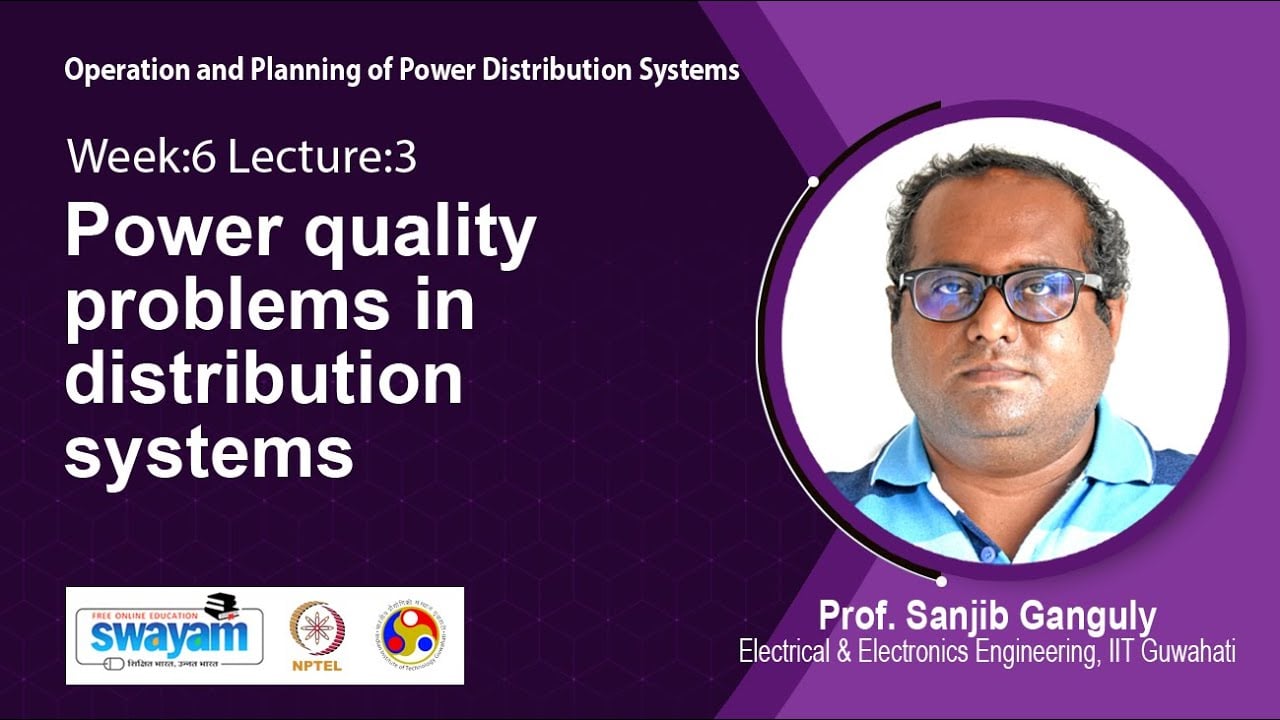
Watch the educational lecture on YouTube.
Frequently asked questions
Does high THDi at low load prove the filter is undersized?
No. Compare the fundamental current, residual harmonic amperes and active operating limits first. Filter sizing and a percentage increase caused by a smaller denominator are different questions.
Can I ignore low-load THDi when harmonic amperes are small?
No. Review the agreed acceptance criteria and site requirements. Small amperes help interpret the result but do not cancel a contractual requirement or resolve measurement uncertainty.
Should the source and load measurements have identical THDi?
Not necessarily. They observe different current paths when a shunt active filter is operating. Name the locations and compare the quantities relevant to the stated objective.
What evidence should I send before requesting a settings change?
Send time-aligned per-phase fundamental currents and harmonic spectra, analyzer settings, operating-state details, filter mode and alarm logs, and a marked single-line diagram. Ask for an approved action tied to that evidence.