
 Zhejiang Hongyan Electric Co., Ltd.
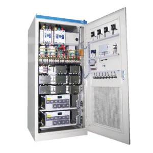
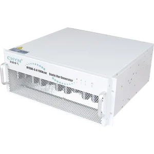
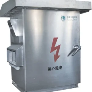
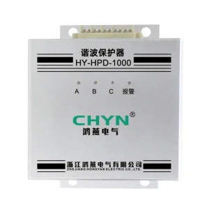
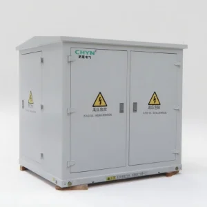
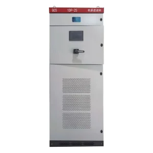
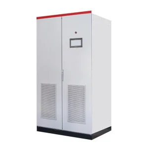
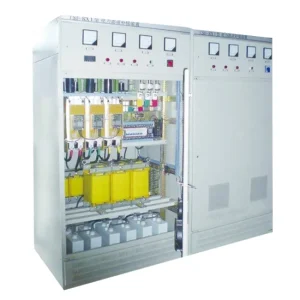
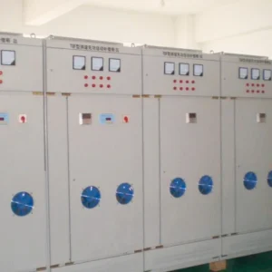
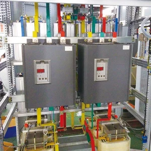
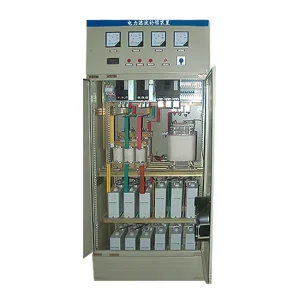
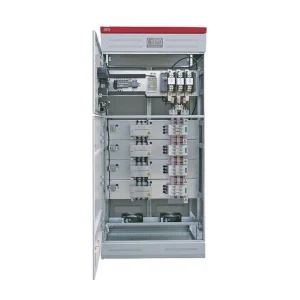
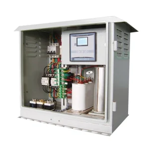
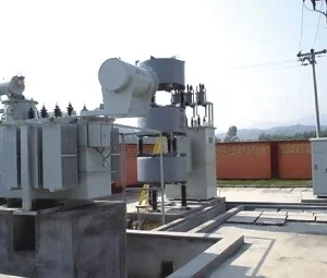
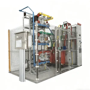
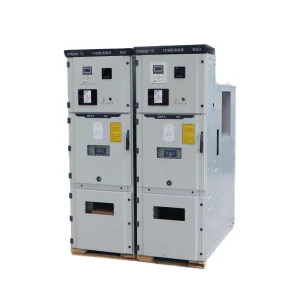
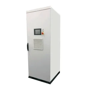
A dynamic voltage restorer for unbalanced voltage sag needs a phase-resolved specification, not only one retained-voltage percentage. Record the source voltages, phase relationships, transformer connections and load requirements, then obtain evidence that the proposed DVR topology can provide the required injection on each relevant phase. A balanced-sag demonstration does not establish unbalanced-sag capability. This guide focuses on procurement and verification of that capability; it does not assign CHYN a universal correction range, response time, zero-sequence function or ride-through duration.
Describe the event at the protected load boundary
An industrial process may trip when one supply phase is depressed even though a three-phase average looks acceptable. A different process may tolerate a magnitude reduction but react to a phase disturbance or a control-supply interruption. Begin with the actual failure: identify which device dropped out, what its input terminals experienced and which protective or control event occurred first.
Locate the disturbance record relative to the DVR injection transformer, any distribution transformer and the sensitive equipment. A source-side recorder and a load-side recorder do not describe the same voltage during compensation. Label the measurement channels, phase sequence and voltage base so that a supplier can interpret the exported waveforms without guessing.
Record whether each voltage is line-to-line or line-to-neutral. If the protected load has a neutral connection, include it in the system description. Do not mix voltage bases in one percentage table. Where the neutral is absent or unsuitable as a measurement reference, use an approved measurement arrangement and state which quantities were measured and which were derived.
Use sequence components to explain the question
NPTEL's chapter on symmetrical components describes resolving an unbalanced three-phase phasor system into component systems. Positive, negative and zero sequence provide an analysis framework. They help specify which voltage components must be considered, but their calculation does not by itself establish that a particular converter or transformer can inject every required component.
Ask the designer to explain the reference convention and the measurement location used for sequence analysis. A negative-sequence result and a simple comparison of the three RMS magnitudes answer related but different questions. Keep the original three-phase waveforms so that an unexpected derived result can be checked against the underlying data.
Zero-sequence behavior needs particular attention to the actual circuit. A statement that a controller can calculate a component is not the same as evidence that the supplied power circuit can compensate it at the load terminals. Request a connection drawing and application explanation for the proposed system rather than assuming all DVR products have interchangeable capabilities.
Ask for topology-specific compensation evidence
The original UFPE master's thesis on modeling, control and performance evaluation of a DVR studies DVR arrangements including a four-arm inverter for zero-sequence compensation. Its conclusions concern the modeled arrangements and study conditions. They illustrate why topology matters; they do not certify CHYN hardware or establish a field performance limit for another installation.
For a proposed unit, request the power-circuit arrangement, injection-transformer connections and the supported system configuration. Ask which unbalanced events have been evaluated and which remain outside the offered operating envelope. The answer should distinguish simulation, laboratory demonstration and evidence for the actual supplied configuration.
Do not require a particular research topology merely because it appears in a paper. The supplier may offer another valid arrangement. The purchasing requirement is a verified load-side outcome under defined source and load conditions, accompanied by a clear explanation of limits and protections. This is more useful than specifying a research controller name without knowing the rest of the power circuit.
Build a phase-resolved event and acceptance matrix
| Event descriptor | Information to provide | Required supplier response |
|---|---|---|
| Phase voltages | Retained voltage and phase relationship by channel | Supported injection and expected residual voltage by phase |
| Duration and recurrence | Event length and interval between events | Duty limits and recovery requirements |
| Network connection | Transformer vector groups, grounding and neutral | Applicable topology and component compensation limits |
| Load operating state | Current waveform and sensitive process condition | Applicable current capability and verification cases |
| Protection response | Trip sequence, bypass status and fault location | Coordinated operating and blocking behavior |
This matrix is a planning tool, not a list of universal test limits. Add quantitative acceptance criteria only when the load owner, equipment supplier and responsible engineer have agreed them. A pass result must identify which row and operating case it covers.
A simple example shows why averaging loses information
Suppose a hypothetical recorder reports retained phase-to-neutral magnitudes of 0.50, 0.80 and 1.00 per unit on a common base during one event. Their arithmetic average is approximately 0.767 per unit. Replacing those three inputs with a balanced 0.767-per-unit test would remove the original asymmetry. It is a different test even though its average matches.
These values are an original illustrative scenario, not a disturbance classification or a CHYN test. Phase angles are deliberately unspecified, so the three magnitudes alone are insufficient to calculate a unique set of sequence components or injection voltage vectors. Retain the full event file instead of converting it into a single rounded percentage.
For the same reason, do not estimate the required converter or stored-energy rating from that average. The detailed calculation needs the selected compensation strategy, load current, duration, phase information and equipment limits. Use the companion discussion of DVR energy-storage sizing inputs when assembling that part of the enquiry.
Separate magnitude restoration from phase restoration
State whether the load requires restoration of voltage magnitude, preservation of its pre-event phase relationship, or another agreed outcome. An acceptance report should describe what was restored and what remained during the event. “Voltage corrected” is incomplete when the sensitive equipment also depends on phase tracking or a separately supplied control circuit.
Ask how the controller establishes its voltage reference during an unbalanced event and how it transitions back after the source recovers. Obtain evidence that shows both the event onset and clearance. A favorable steady portion of a trace cannot describe every transition experienced by the process.
Phase displacement deserves its own event case when it matters to the load. The guide to DVR phase-angle jumps addresses that input in more detail. Keep it distinct from the present question of unequal phase disturbances and connection-dependent compensation, while including both in a combined acceptance case if the actual site event contains both.
Keep protection and load continuity in the same review
Determine whether an event originates upstream of the protected load or includes a downstream fault. The offered DVR should have an explicit operating response for the relevant case. Do not ask the supplier to maintain a load voltage by defeating a protective action or overriding a documented blocking condition.
Include bypass operation, protection indications and the state of the injection system in the event record. A process interruption can occur through a coordinated transfer or protection action even when the available injection voltage would otherwise appear sufficient. Investigate the sequence of events rather than treating every interruption as a failure of voltage capacity.
Control power also belongs in the review. Identify which auxiliary supplies remain available during the agreed event and which process devices depend on separate circuits. A corrected main power input does not establish continuity for an independently supplied PLC, contactor coil or communication device.
Request evidence that can be checked independently
For an enquiry concerning the CHYN HYDVR voltage-sag mitigation solution, attach a marked single-line diagram and original event files. Provide the load's actual current and operating state, the source configuration, voltage base, event duration and required outcome. List which data are measurements and which are assumptions awaiting confirmation.
Ask for source, injected and load voltages on a common time axis, together with load current and the relevant converter or energy-store status. The report should identify the unit configuration and test method. A demonstration from another rating can be useful background, but it should remain labeled as such until its applicability is justified.
Plan the commissioning cases with the supplier and site engineer. Use approved test equipment and procedures; do not create uncontrolled faults on a live plant to reproduce a sag. If a particular event cannot be tested on site, identify the alternate evidence and leave the limitation visible in the acceptance record.
Close the review with a case-by-case decision
The final report should separate verified operating cases from conditional or unsupported cases. For each one, record the input disturbance, configuration, expected result, observed result and remaining conditions. If the test setup differs from the final installation, state the difference and the engineering basis for applying the result.
Maintain those records with the maintenance and configuration files. A later transformer change, load expansion or grounding revision may affect the original assumptions. Revisit the relevant cases when such a change occurs rather than treating the initial demonstration as permanent evidence for every future network arrangement.
For a broader plan that includes instrumentation, procedures and acceptance documentation, use the DVR acceptance-test planning guide. A complete plan should make the unbalanced cases explicit so they remain visible from enquiry through commissioning.
Educational video: symmetrical component analysis
The following NPTEL lecture explains symmetrical component analysis. It supports the analysis vocabulary used in an unbalanced-event discussion; it is not a DVR product demonstration or evidence of CHYN's correction capability.
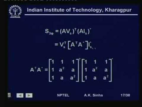
Watch the educational lecture on YouTube.
Frequently asked questions
Does a balanced-sag test prove unbalanced-sag performance?
No. An unbalanced event can require different phase injections and involves connection-specific limits. Request evidence for the actual event matrix and supplied configuration.
Are three retained-voltage magnitudes enough to specify the event?
No. Retain the voltage reference, phase relationships, duration, measurement location and connection details. Magnitudes alone do not uniquely describe the relevant voltage vectors.
Can every DVR compensate zero-sequence voltage?
Do not assume so. Obtain a topology-specific explanation and evidence for the proposed transformer, converter, grounding and neutral arrangement.
What determines whether an unbalanced test passes?
The agreed load-side criteria for each defined operating case, supported by synchronized measurements and documented equipment conditions. No single average voltage or generic response-time claim establishes acceptance.