
 Zhejiang Hongyan Electric Co., Ltd.





































Capacitor bank installation for a packaged shunt bank runs in one order: confirm the site, land the enclosure, connect isolation then cable, ground, and discharge, finish the checks before the isolator closes, and leave a handover record.
Once the order is frozen, walking from the pad to the handover record is how to install capacitor bank. A shunt capacitor supplies leading reactive power beside inductive load, so the feeder carries less of the reactive current the motors would otherwise pull.
Power factor correction capacitor installation here means setting an already specified outdoor cabinet. The drawings should already say whether this box lands on the main board, a local board, or beside one large motor.
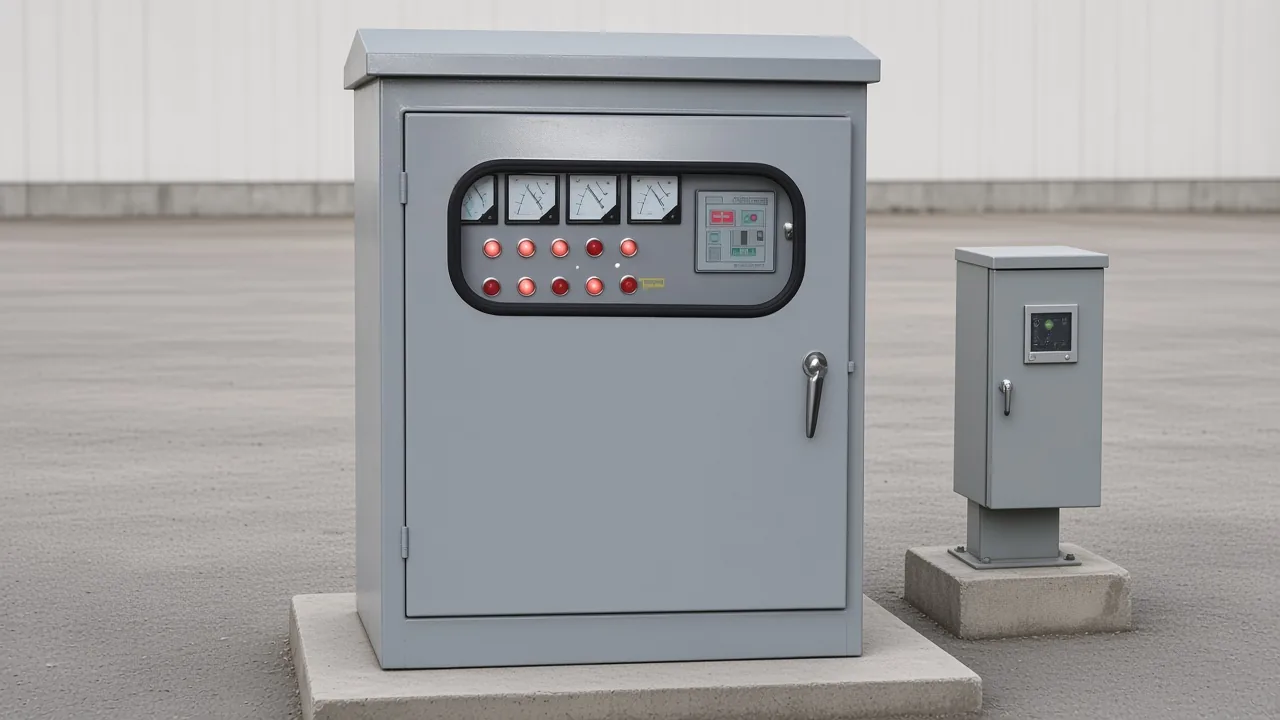
Confirm the Site Before the Enclosure Is Set
Confirm pad or wall, airflow, door swing, and an isolation point before the box is landed, and take clearance from the outline drawing rather than a guessed inch value.
Site readiness covers the pad or wall, the air path, the door swing, and a feeder that can be opened. Plainly, the place has to stay stable, the door has to clear, and someone has to be able to switch the feeder off.
Flat support matters because a rocking cabinet stresses glands and door seals. Air has to move because the cans shed heat, and a door that cannot swing blocks the isolation step that comes next.
Indoor packages need room to breathe and to open. An outdoor cabinet has to live in weather, which is why outdoor structure code W shows up on the live unit, while the outdoor-box copy still gives no inch clearance.
Anchor bolts and the gap around the cabinet come from the outline drawing that ships with the order. Copying an inch value from another vendor's manual would paste the wrong gap onto this cabinet.
Local capacitors raise power factor by supplying reactive power beside the load, so reactive current need not all come from the utility. Switching those steps can disturb voltage if harmonics and a light load were left out of the earlier design.
Bus placement for a 33/11 kV yard stays on the 33/11 kV substation page.
Read the frozen inputs on the capacitor bank design page and leave that checklist there. Rebuilding kvar targets or the order sheet would turn a landing job into a second design pass.
| Step | What you confirm | Stays with another page |
|---|---|---|
| Site | Pad or wall, airflow, door swing, isolation point | Design checklist and substation bus layout |
| Set | Cabinet on the pad or wall, cable entry toward the feeder | Pole hardware |
| Connect | Isolation, cable check, earth, discharge path | Panel terminal map |
| Pre-close | Phase order, empty enclosure, light-load mode | Controller programming |
| Handover | As-built tie-in, nameplate, isolation point, outline-drawing pointer | Inspection calendar |
Land the Outdoor Enclosure Without a Pole Job
Set the outdoor cabinet on the prepared pad or wall, with cable entry toward the feeder, and keep pole-line hardware on its own job.
Mechanical placement covers orientation, cable entry, and a stable mount. Cable glands should face the feeder run so the conductors are not forced into a tight bend at the gland.
Pole hardware lives on the pole-mounted bank page. A packaged cabinet uses a pad or a wall, and it does not use crossarms.
Set the base so the cabinet does not rock when the door is open. A feeder jammed into a gland is the bend crews already complain about, so give the cables a gentle path before the bolts are final.
Walk the sheet metal for transit dents, leaks, and joints that shook loose before the bolts go in. Capacitors should be free of breaks, and factory joints should still be tight after the truck ride.
Heavy-gauge earth lands later on the designated ground terminal. The mechanical step only has to leave that terminal reachable and the base sitting flat.
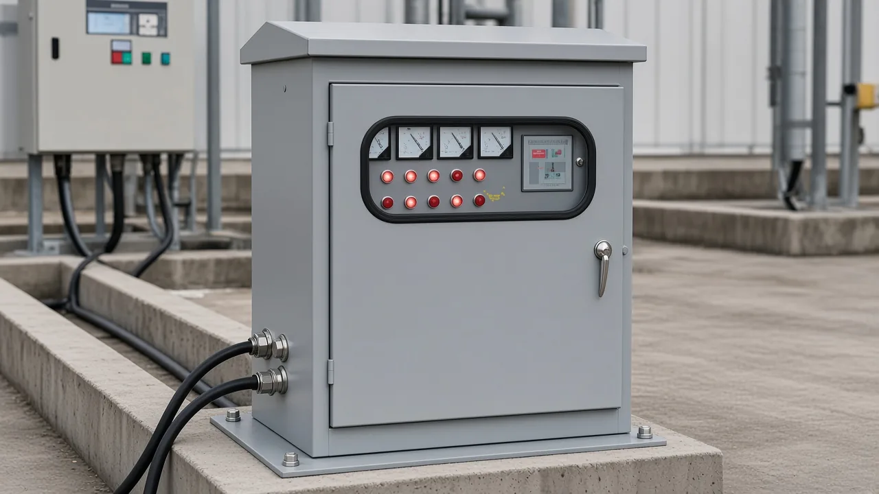
Fixed vs automatic bank was locked when the order was placed. A static cabinet stays on whenever the isolator is closed, while an automatic or hybrid cabinet can step, and that choice only changes the current-transformer note ahead.
Connect Isolation, Cable, Ground, and Discharge
Start with the feeder off and locked, then land power cables checked well above nameplate current, the equipment earth, and a discharge path.
Guides often quote a residual under 50 V within a minute. The nameplate on the cabinet wins when the two lines disagree.
Call the first electrical step Isolator / lockout: the feeder stays open until the later checks finish. The bank can still hold charge after that switch opens, so the feeder must not come back on its own.
29 CFR 1910.147 addresses unexpected energization and the release of stored energy during servicing. It excludes utility generation, transmission, and distribution, and it is not the installation code for this outdoor box.
Shipping damage belongs in this pass too: dents in the sheet metal, capacitors with breaks or leaks, and bus joints that loosened in transit. Land cables only after that walk, and only on a feeder that is open and locked.
Power cable check asks whether the feeder conductors sit above capacitor rated current. Standards allow about 1.3 times nominal current continuously, and capacitance can sit about 10 percent high, so the usual check lands near 1.43 times nominal current.
Treat the nameplate current as incomplete.
Grounding means the equipment earth at the designated ground terminal, run in a heavy-gauge conductor. A paint scratch is not that bond.
Look for the discharge path, the bleeder or discharge device that lets the bank lose its charge after power is removed. Installers expect that path, and reclosing onto a charged bank is a known failure mode.
Wait out that path before anyone works the terminals again. The generic residual line is a cue, and the nameplate still wins.
Place the current transformer on the supply side of an automatic box. Downstream, the controller cannot see its own correction and may switch every step in.
Terminal pictures stay with APFC panel control wiring and the APFC relay control wiring diagram. Those pages own the pins.
Ignore posts that tell you to land a three-phase bank on a positive bus and a negative bus. An AC shunt bank is not wired that way.
| Order | Action | Stop line |
|---|---|---|
| 1 | Feeder off and locked | Cables stay off a live feeder |
| 2 | Power cable check above nameplate current | Do not guess a cable size; stop if the feeder is only at nameplate current |
| 3 | Equipment earth on the designated terminal | Paint is not the bond |
| 4 | Discharge path in place | Wait, then read the nameplate |
| 5 | Current transformer on the supply side when the box is automatic | Panel pages own the terminals |
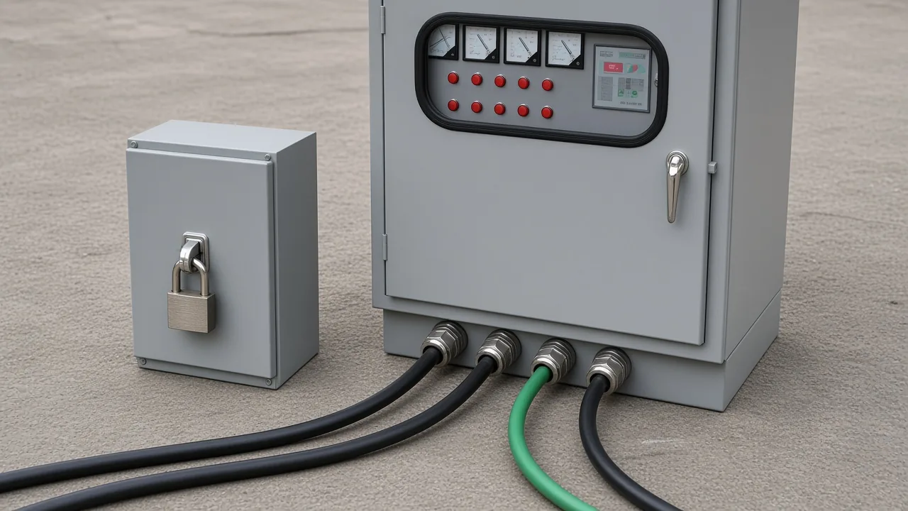
Check Phasing and the Enclosure Before Close-In
Match phase order, clear tools and loose hardware, and keep a fixed bank offline if the night load will fall away.
Pre-energization checks cover phase order, a clear enclosure, and a mode that can step out when load drops. Capacitor bank commissioning starts while the isolator is still open.
Match L1, L2, and L3 to the supply before the isolator is closed. Wrong phasing is a named commissioning failure and can damage the equipment.
From the field: Crews have found needle-nose pliers left on a live bank. A kinked feeder heats, so treat that bend as damage rather than a tidy-up item. — electrician field report
Watch the night load before you close in. A fixed bank that cannot step out is the wrong thing to leave energized when motors stop after hours.
One plant question described motors idle overnight while the bank stayed fully online, so power factor went leading. The reply on that Physics Forums thread was to take capacitor steps offline once reactive output runs ahead of the remaining load.
Shunt power capacitors are brought on while the plant is loaded and taken off when the plant idles, which keeps a light feeder from sitting leading. Unbalance protection watches neutral current or voltage after a unit fuse operates, so one failed unit does not overstress the rest.
Drop any temporary shorting link on a current transformer before the protective device closes, if the drawing used one. Close that device only after phase order and the empty-enclosure look agree.
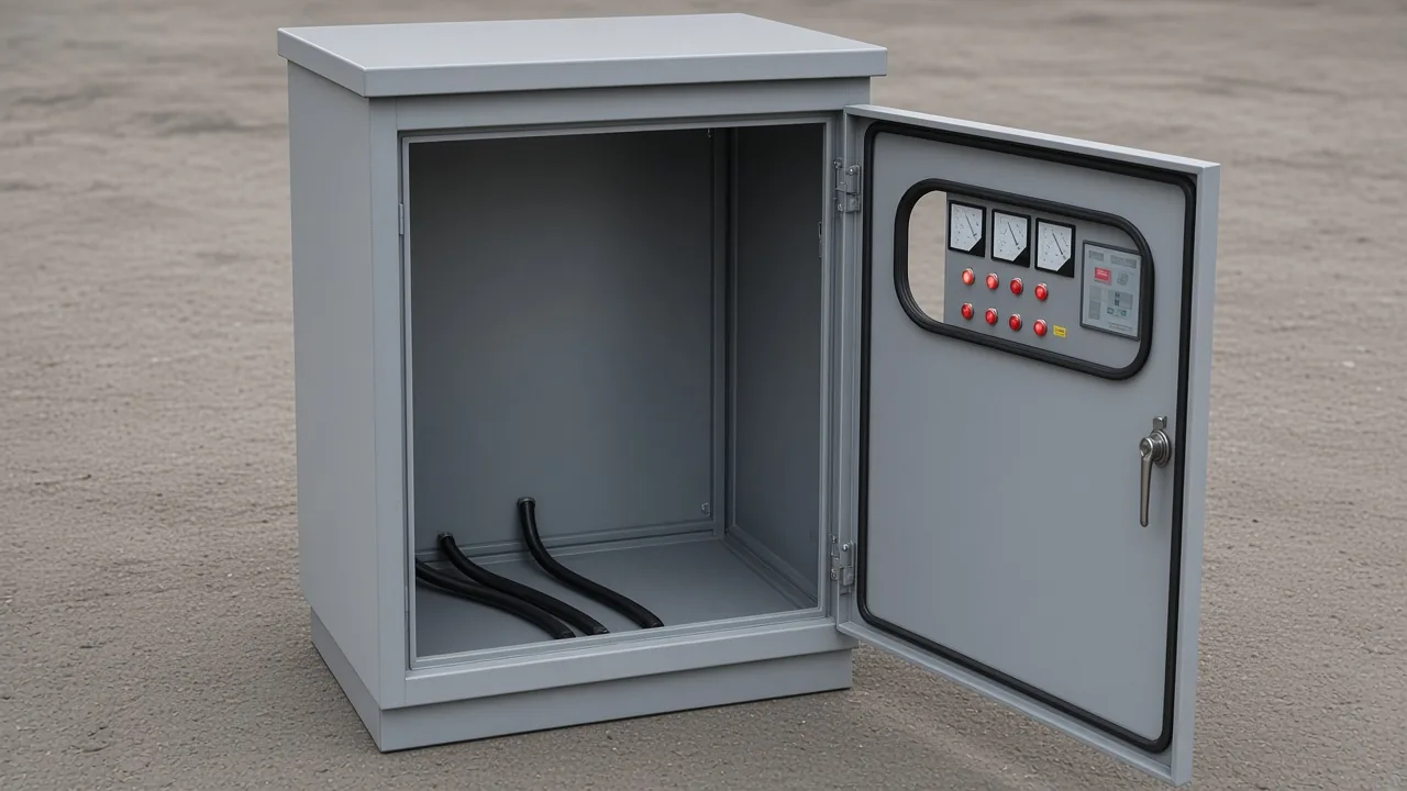
Leave a Handover Record the Next Crew Can Use
Leave the as-built tie-in, the nameplate, the isolation point, and a note that the outline drawing holds clearance and torque.
Handover record means the packet the next crew can use without guessing. It holds the as-built tie-in, the nameplate, the isolation point, and a pointer to the outline drawing for sizes the outdoor-box copy does not state.
Clearance, torque, cable-entry detail, and any kvar figure live on that drawing. The marketing line does not carry them.
Photograph the nameplate and the isolation point while the crew is still on site. Write which board the cables landed on, so the next person does not have to trace the feeder by guess.
A large utility package once listed foundation notes, embedded conduits, schematics, and a bill of materials. This cabinet handover is smaller, and the same idea holds: the next crew should not rebuild the tie-in from memory.
After handover, inspection cadence belongs to capacitor bank maintenance.
Which Outdoor Box Fits This Capacitor Bank Installation
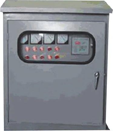
The HYTBB outdoor compensation box fits when the job is a packaged outdoor cabinet, not a pole, a panel drawing, or an open design.
That HYTBB outdoor box serves distribution transformers, low-voltage feeders, and outdoor distribution. Open the LV compensation category for the series path, and treat the cabinet as a low-voltage outdoor box rather than a high-voltage substation bank.
The model example HYTBBJL-0.4-□/□W-P7 names a 0.4 kV system and outdoor structure code W. Blanks in that code are not a published kvar range.
Order the box fixed, automatic, or hybrid, and manual intervention is also named. Zero-crossing switching is named, and protections cover over-voltage, under-voltage, short-circuit, over-current, unbalance, and harmonic.
Monitoring named on the page includes voltage and current on each phase, plus power factor, power, temperature, capacitor current, and switching state, with optional GPRS. J marks a static branch, D a dynamic branch, P a reactor branch, and H a harmonic-filter branch.
The slogan about easy installation, stable operation, and convenient maintenance is sales language. It is not a procedure.
Those published lines leave out clearance, ingress rating, ambient, altitude, torque, and a numeric kvar range. Take those from the outline drawing, then open the product link for the mode list and the protection list.
FAQ
What site conditions must be true before a capacitor bank is set in place?
The pad or wall has to be stable, the door has to swing, air has to move, and the feeder has to have an isolation point. Take any inch clearance from the outline drawing that ships with the cabinet.
How do you connect a capacitor bank once the enclosure is in place?
Open and lock the feeder first, then land the power cables, the equipment earth, and the discharge path. If the cabinet is automatic, keep the current transformer on the supply side, and leave pin names to the panel wiring pages.
Does it matter which way you install a capacitor bank?
Enclosure orientation and cable entry matter, and phase order matters before close-in. A three-phase bank is not a direct-current stack with a positive bus and a negative bus.
What should be checked before a capacitor bank is energized?
Match phase order, confirm joints did not shake loose, and confirm the enclosure holds no tools or loose hardware. Confirm the discharge path is present, and set the protective device the way the drawing says.
What should the handover package show after capacitor bank installation?
Show the as-built tie-in, the nameplate, and the isolation point. Add a note that the outline drawing, rather than the marketing page, holds clearance and torque.
How is capacitor bank installation different from an APFC panel wiring diagram?
This landing order stops at site, set, isolation, cable, ground, discharge, pre-close checks, and the handover record. Panel terminal maps stay on the live APFC wiring pages, pole hardware stays on the pole page, and design inputs stay on the design page.
What is the purpose of a capacitor bank?
A capacitor bank supplies reactive power next to inductive plant load so the feeder carries less of that current. Switching steps can disturb voltage if harmonics and light load were ignored.