
 Zhejiang Hongyan Electric Co., Ltd.





































A fuseless capacitor bank connects capacitor units in series strings and leaves out both an internal element fuse and an individual external unit fuse. A failed capacitor element is described as welding into a short, so the capacitor unit can remain in service while voltage rises on the remaining series sections. That missing fuse is the plant-bus choice: what stays connected after one element fails, and what a walkdown can still see.
An internally fused capacitor bank clears one element inside the can. An externally fused capacitor bank puts the fuse outside the unit, where a blown fuse is the visible marker. Unfused capacitor banks are a parallel-group arrangement.
Indication then looks for a short rather than a blown fuse. HYTBB prints shunt-cabinet ratings without naming a fuse scheme.
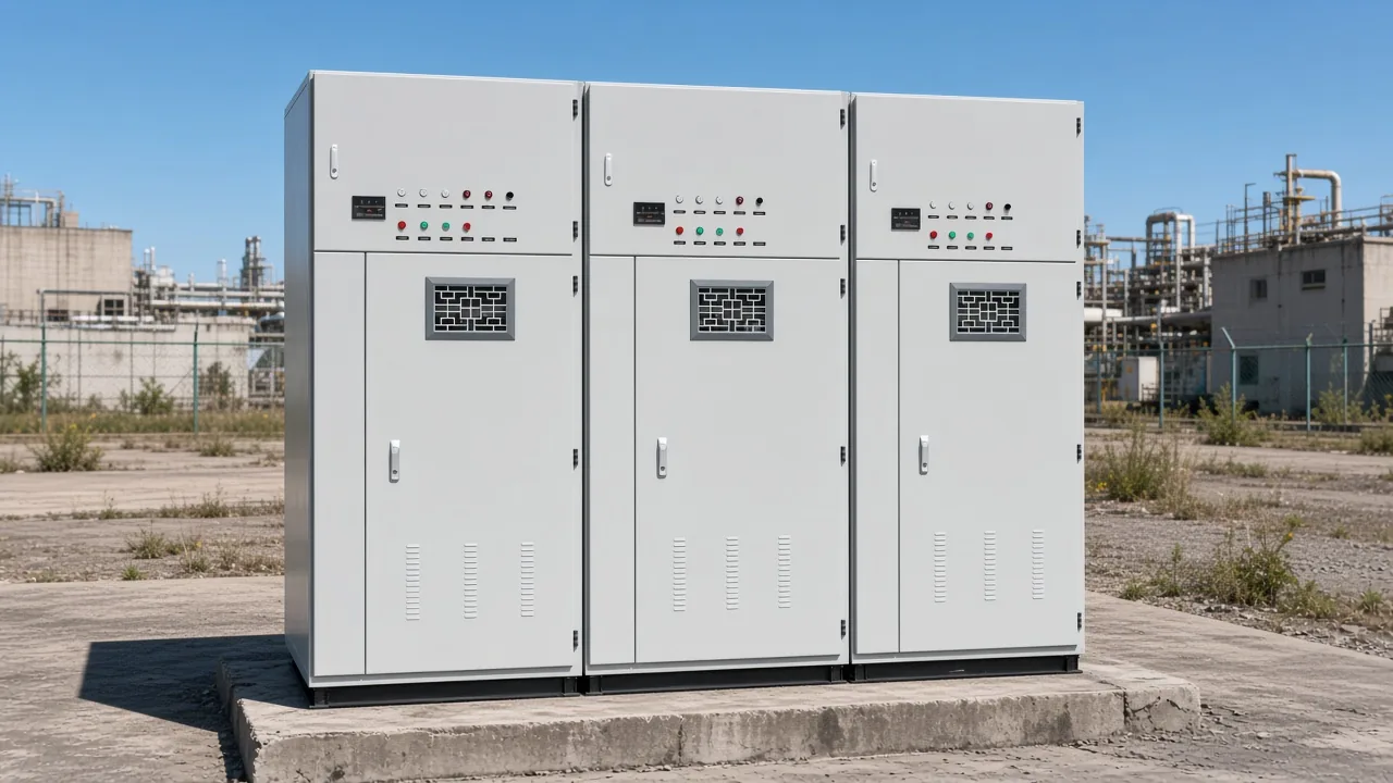
What a fuseless capacitor bank means on a plant bus
A fuseless capacitor bank on a plant bus is a shunt capacitor bank whose capacitor units sit in series strings, with no element fuse inside the can and no individual fuse outside it. When one capacitor element fails, the usual description is a welded short, the capacitor unit can stay in operation, and the remaining series sections share a higher voltage.
On the rack, the series path is the stack of capacitor units between phase and neutral, or between the bus and the string end. The capacitor element is the internal section inside a capacitor unit. A weld shorts that section, the string stays up, and the voltage that section used to hold moves onto the sections that remain.
Tom Ernst, writing for Minnesota Power, names internally fused, externally fused, and fuseless as three main types of power capacitors. In that account a fuseless unit can continue with a slightly reduced VAR rating, because the overvoltage on the unshorted groups is smaller than the rise that would follow a cleared fuse. The bank comes off if voltage stress becomes high enough to cause cascaded failure.
The 1999 PG&E and SEL paper describes a fuseless unit as a few elements in parallel and many in series, with the bank connecting capacitor units in series. One element failure produces a small voltage rise shared along that string. Today’s film units, in that paper, weld foil on a puncture instead of sustaining the arcing described for older kraft-paper units.
One short in the course illustration of 6 series units and 8 element groups, 48 groups in all, is described as 48/47, around a 2% voltage increment. The 1999 PG&E and SEL paper names new fuseless installations at 115 kV and 230 kV. Those two installation voltages are that paper’s examples.
A technical account of the three constructions adds the maintenance limit. String-current change may be small. The bank stays in service only while the failed-element count and the calculated overvoltage stay inside the design’s alarm and trip limits.
A 2001 conference paper describes a fuseless bank as multiple series strings in parallel with no interconnections between strings. That description is the plant-bus picture: parallel strings, series units inside each string, and no fuse assigned to the element or to the individual capacitor unit. The relay protection paper on multi-string fuseless banks keeps the worked bank figures with that paper.
| Arrangement | What fails or opens | What is removed | What a walkdown can see |
|---|---|---|---|
| Series-string fuseless | Capacitor element welds short | No fuse clears the element | No blown fuse; voltage rises on the remaining sections |
| Internally fused capacitor bank | Element fuse opens | One capacitor element | No rack fuse; the sealed capacitor unit is what gets replaced |
| Externally fused capacitor bank | External fuse operates | The whole capacitor unit | A blown fuse on the rack |
| Unfused capacitor banks | No element fuse and no unit fuse | Parallel groups remain in series | No fuse marker; the layout is parallel groups in series |
How an internally fused bank isolates one element
An internally fused capacitor bank puts a fuse on the capacitor element inside the capacitor unit. One failure removes only that element, and the capacitor unit and the bank can remain in service.
The 1999 PG&E and SEL paper states that an element failure and subsequent isolation removes only a small part of the capacitor unit. Internal fusing does not put a blown fuse on the rack. Field maintenance replaces the sealed capacitor unit, because the failed capacitor element is not visible from outside the can.
Many elements sit in parallel inside that can, so losing one of them is a small slice of the capacitor unit. The string, or the parallel group, keeps its other elements. The rack still looks complete, which is why a walkdown that only hunts for a hanging fuse will miss this failure.
That marker differs from the series-string short on a fuseless capacitor bank. Here the fuse did operate, but it operated inside the can. The capacitor unit stays connected, and the early sign is unbalance or a capacitance change, with no link lying open on the steel.
How an externally fused bank removes a whole unit
An externally fused capacitor bank uses a fuse outside the capacitor unit, and that fuse is intended to remove the failed unit. A blown fuse is the visible marker on the rack.
The 1999 PG&E and SEL paper says intact fuses do not necessarily mean the capacitor units are in perfect operating condition, and a failed fuse does not necessarily indicate that the capacitor unit has failed. An externally fused can often continue after one element failure until cascading failure blows the external fuse, which is the path the Minnesota Power paper describes.
Open-rack descriptions of an externally fused capacitor bank put an expulsion fuse or a current-limiting fuse on each capacitor unit. Many units sit in parallel in each series group, so the fuse is a unit device, rather than an element device.
Seeing the fuse intact answers where the unit still connects. It does not inventory every capacitor element inside the can.
A poster on a Mike Holt thread separates an internal fuse, which clears a shorted series element inside a high-voltage capacitor, from an external fuse, which clears a short at the capacitor terminals.
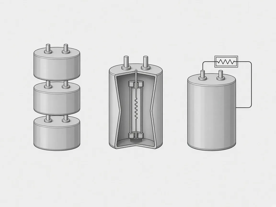
A buyer at the rack can point at the fuse. Reading it still takes the paper’s split: the link is there to take the capacitor unit out, and the link position is weak proof that every internal section is healthy.
A blown fuse is a reason to inspect that position. The open link, by itself, falls short of proof that the capacitor unit failed.
Why unfused is a different arrangement
In the PDH course, fuseless units are linked in series, while an unfused shunt capacitor bank applies a series/parallel arrangement of units with no fuses. Unfused capacitor banks keep parallel groups in series and simply omit fuses, both inside the can and outside it.
The capacitor bank course EE-04-922 draws that line in one place: opposite to the fuseless arrangement, where the units are linked in series, the unfused layout is the series/parallel stack. A handbook section uses the same split. Unfused banks follow fused banks in using parallel groups in series, but there are no fuses either internally or externally.
Treating every bank that lacks a fuse as one product hides that split. A series chain shares a shorted element’s voltage along the remaining sections of that chain.
A parallel-group stack without fuses still has the group geometry of a fused bank, minus the links. The walkdown, the spare can, and the unbalance story follow the geometry, rather than the single phrase “no fuse.”
What changes in protection when no fuse operates
With no fuse operation to inspect, indication moves to unbalance protection, voltage measurement, or impedance measurement. The Minnesota Power paper says there is no outward indication of which cans have bad elements, so alarming for one failed element may not be useful for maintenance.
On that paper’s fuseless application, element failures increase phase current and the difference voltage becomes smaller. Blown fuses on a fused bank, in the same account, reduce phase current and increase the difference voltage. The current direction is that protection module’s contrast, and it is the reason a fused-bank unbalance habit can be read backwards on a series string.
These protection texts use about 110% of rating as the stress level at which remaining elements should not be left in continuous service. The PDH course says a permanent overvoltage higher than 10% on any element is to be stopped by relays.
Both lines belong to those protection texts. They are stress language for remaining elements after failures, and they stay apart from any cabinet voltage multiple printed for long-term or short-duration operation.
From the field: On a fuseless bank the protection concern shifts toward detecting the short, and both that short and a fuse operation cause overvoltage. — Eng-Tips thread
The Idaho thesis says one tradeoff with this design is the lack of visible fault indication present on fused banks, so the relays are the first line of protection. The Idaho thesis on fuseless shunt capacitor bank protection keeps its model bank with the thesis. The Minnesota Power paper on fuseless capacitor bank protection is the source for the reversed difference voltage and for the point at which one more failure would push remaining elements past the stress it names.
Substation technicians name internally fused, externally fused, and fuseless together when they list the bank types a protection discussion has to cover. The practical split is what the early alarm is hunting.
A fused rack can start with a blown fuse. A series string starts with a shorted capacitor element and a measurement.
What the HYTBB product prints, and what it does not print about fusing
HYTBB is a shunt capacitor cabinet for compensating inductive reactive power, and that description does not name a fuse arrangement. The cabinet lists overcurrent, overvoltage, unbalanced load, and short-circuit protection, which still leaves the unit-fuse choice unnamed.
The overview states rated voltages from 1 kV to 35 kV. The parameter table states rated voltage as 10(6)–35 kV. Those two voltage statements stay apart, because the overview span and the parameter-table span are different printed lines.
The parameter table states rated frequency as 50 Hz. The parameter table states rated capacity as 50–20,000 kvar. Frequency on the cabinet is that 50 Hz row alone.
The neutral row is printed as isolated neutral or non-effective grounding. Isolated neutral is one phrase in that row. Non-effective grounding is the other phrase, and the two phrases stay side by side.
Residual voltage drops below 50 V within three minutes after disconnection. Residual voltage drops below 50 V within five minutes after disconnection, on the discharge resistors of each capacitor group. A course note that an internal discharge resistor reaches 50 V or less in 5 min belongs to that course, beside the cabinet’s three-minute line and beside the cabinet’s five-minute line.
Long-term operation is printed at 1.0× rated voltage. Short-duration withstand is printed up to 1.3× rated voltage.
Those two cabinet lines are the printed voltage multiples. They stay apart from the protection texts’ about 110% stress line.
The performance-features sentence prints a power factor up to 0.95 or higher and a line-current reduction of 10–20%. That sentence is the cabinet’s performance-features claim. It is a printed statement about power factor and line current.
Readers who need that shunt-cabinet job can use the high-voltage power factor compensation series and the HYTBB medium and high voltage reactive power compensation cabinet. The high-voltage series repeats the shunt-bank summary and does not add a fuse scheme.
| Printed item | Wording kept |
|---|---|
| Overview voltage | 1 kV to 35 kV |
| Parameter-table voltage | 10(6)–35 kV |
| Rated frequency | 50 Hz |
| Rated capacity | 50–20,000 kvar |
| Neutral connection | Isolated neutral or non-effective grounding |
| Residual voltage, performance features | Below 50 V within three minutes |
| Residual voltage, discharge resistors | Below 50 V within five minutes |
| Long-term voltage | 1.0× rated voltage |
| Short-duration voltage | 1.3× rated voltage |
| Fuse arrangement | Not printed |
A buyer can read those rows for the shunt-cabinet duty and still have to ask which fuse arrangement applies. HYTBB does not identify the fuse arrangement. Treating the cabinet as fuseless, internally fused, externally fused, or unfused would add a construction the printed rows do not state.
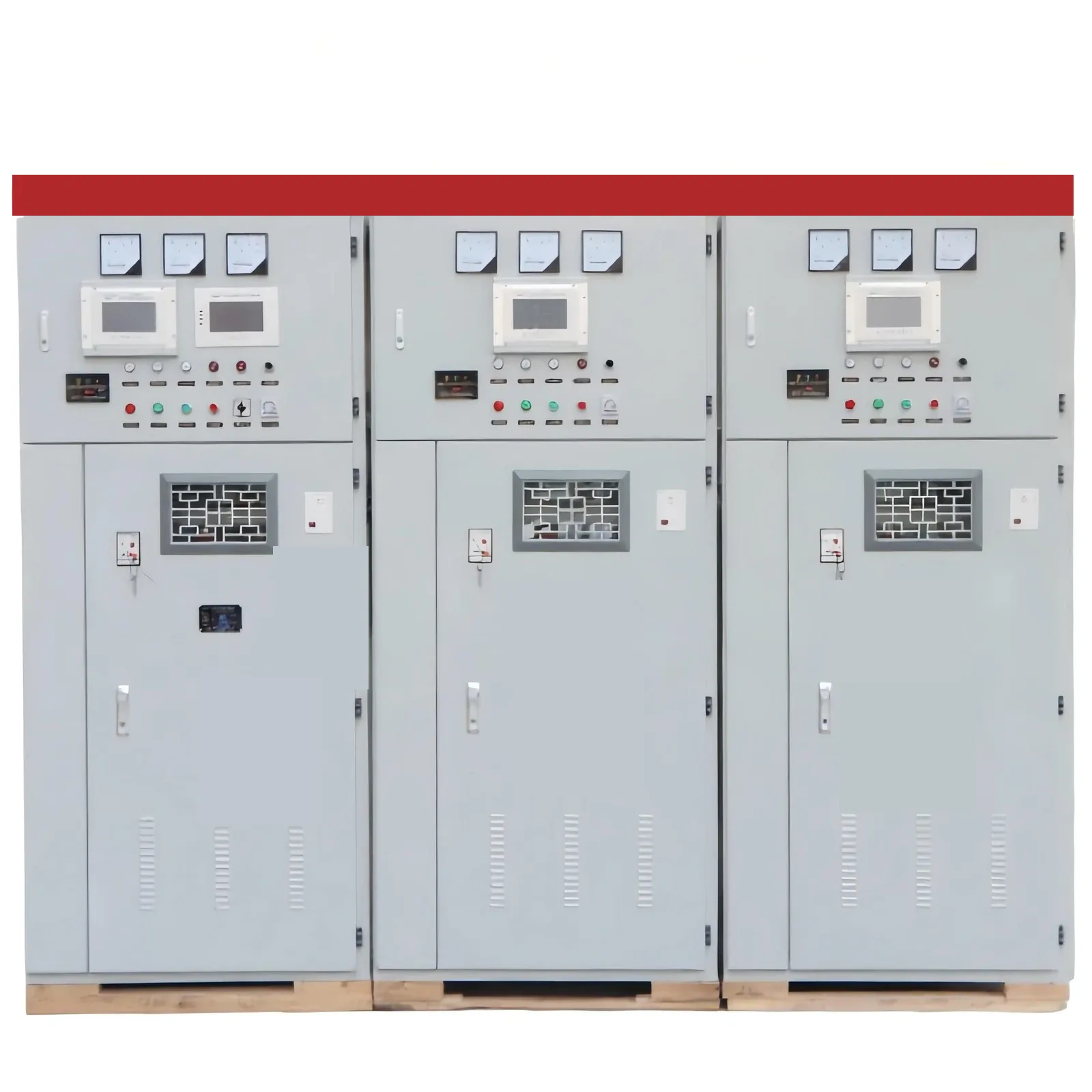
What to ask before treating a cabinet as fuseless
That course remark belongs to the course, not to the cabinet voltage rows. The PDH course says the fuseless series-chain design is not typically used below about 34.5 kV, because more than 10 elements in series are wanted.
The course wants more than 10 elements in series so that one failure does not force the bank offline. That element count is the course’s reason for the voltage remark, and it is not a cabinet trip setting.
Eaton’s open-air catalog lists externally fused, fuseless, and internally fused designs. The per-unit bands on that catalog are 50–700 kvar, 50–1000 kvar, and 200–1200 kvar.
Southern States lists external fuse, internal fuse, or fuseless on its open-rack and metal-enclosed tables. Open-rack voltage on that catalog runs from 4.16 kV to 345 kV. Metal-enclosed voltage on that catalog runs from 4.16 kV to 38 kV.
The open-rack and metal-enclosed ceilings above are Southern States catalog limits.
Before anyone calls a cabinet fuseless, the questions are the ones the constructions actually change. Is the layout a series string, an element fuse inside the capacitor unit, an external fuse on the capacitor unit, or parallel groups with no fuses?
Which signal appears first: a blown fuse, or unbalance protection with no fuse to inspect? Which voltage line is being quoted: a course remark, a catalog row, or the cabinet’s own printed lines?
General shunt protection sits in shunt capacitor bank fundamentals and protection. Neutral grounding sits in ungrounded capacitor bank.
Phase connection choices sit in capacitor bank wiring. Reactor detuning sits in why use a reactor in a capacitor bank.
FAQ
What does a fuseless capacitor bank mean on a plant bus?
It means capacitor units tied in series strings, with neither an element fuse nor a separate unit fuse. One failed section is expected to weld short while the string remains up and the other sections carry more voltage.
How is an internally fused capacitor bank different when one element fails?
The fuse that opens is on the element, inside the can, so only that element is cleared. The capacitor unit can stay connected, and the failed section is hidden from a rack walkdown.
How is an externally fused capacitor bank different when one unit fails?
The fuse sits outside the can and is meant to disconnect that whole unit. A link that has opened is visible, yet an intact link is weak evidence that every internal section is sound, and an open link is weak evidence that the can itself failed.
Is an unfused capacitor bank the same as a fuseless capacitor bank?
No. Unfused capacitor banks keep a series/parallel stack of units and simply leave the fuses out. The fuseless layout is the series chain, so the two names are different geometries.
Why is there no blown fuse to inspect on a fuseless bank?
Nothing in that arrangement is assigned to melt and drop out when one element shorts. The early sign is a relay measurement, because the cans give no outward mark of which element welded.
Does the HYTBB page state whether the cabinet is fuseless or fused?
HYTBB lists overcurrent, overvoltage, unbalanced load, and short-circuit protection. It leaves the fuse arrangement unnamed, so the cabinet cannot be classed from the printed rows.
Can the cabinet’s 50 Hz row be read as a 60 Hz rating?
Rated frequency in the parameter table is the 50 Hz cell alone. A second system frequency is absent from the cabinet record.
Are fixed and automatic banks the same choice as fuseless and fused banks?
Fixed banks and automatic banks answer how the bank is switched. Fuseless and fused constructions answer what clears, or fails to clear, after one element or one unit fails.
References
- Tom Ernst, Minnesota Power, on fuseless capacitor bank protection
- Velimir Lackovic, capacitor bank course EE-04-922
- Zachary Martin, impedance-based protection for a fuseless shunt capacitor bank
- Leo Fendrick and coauthors, relay protection of multi-string fuseless capacitor banks
- Mike Holt forum, overcurrent protection for capacitors