
 Zhejiang Hongyan Electric Co., Ltd.






































How to calculate reactive power starts with the inputs you already have. Most plant boards give you either real power and power factor, real power and apparent power, or voltage, current, and phase—and capacitors need C, frequency, and the voltage across the bank. The sections below map those paths for single-phase and three-phase feeders, run labeled educational arithmetic, flag metering and sign mistakes, and show where an outdoor HV shunt bank sized from required kvar fits after the number is known.
Keep the power triangle in view: when waveforms stay sinusoidal, S² = P² + Q². Honest P and S (or P and PF) from the same interval are what unlock Q—and that is how to calculate the reactive power without guessing.
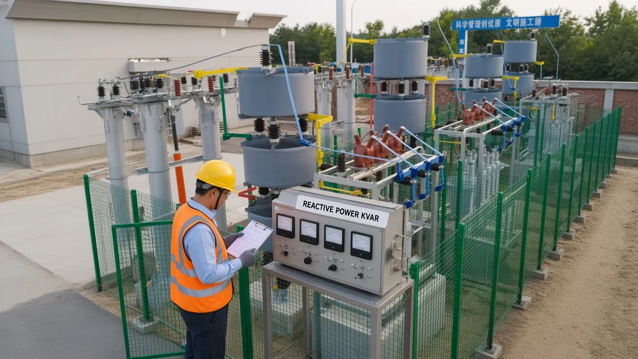
Core Formulas: How to Calculate Reactive Power from V, I, S, and P
Pick Q = Vrms × Irms × sinφ or Q = √(S² − P²) from the inputs you have. Reactive power is the quadrature leg of AC power and is measured in var (often kvar).
Independent formula sheets state the single-phase RMS identities Q = Vrms Irms sinφ, P = Vrms Irms cosφ, and S = Vrms Irms, with S² = P² + Q² on the power triangle (Atlas of Engineering AC power formula sheet). University circuit teaching rearranges the same triangle as Q = √(S² − P²) and Q = S sinθ (LibreTexts power triangle).
Encyclopedia and standards-topic pages keep the unit as var and the common load sign convention: inductive Q positive, capacitive Q negative (Wikipedia AC power; IEEE Technology Navigator on reactive power).
| Available inputs | Formula for Q | Typical plant units |
|---|---|---|
| Vrms, Irms, phase angle φ | Q = V × I × sinφ | VAR or kvar |
| Apparent S and real P | Q = √(S² − P²) | kvar from kVA and kW |
| Real P and power factor PF | Q = P × tan(arccos PF) | kvar from kW and PF |
| Current and reactance X | Q = I² × X | VAR (signed by X) |
Keep units consistent. If P is in kW and S is in kVA, Q comes out in kvar.
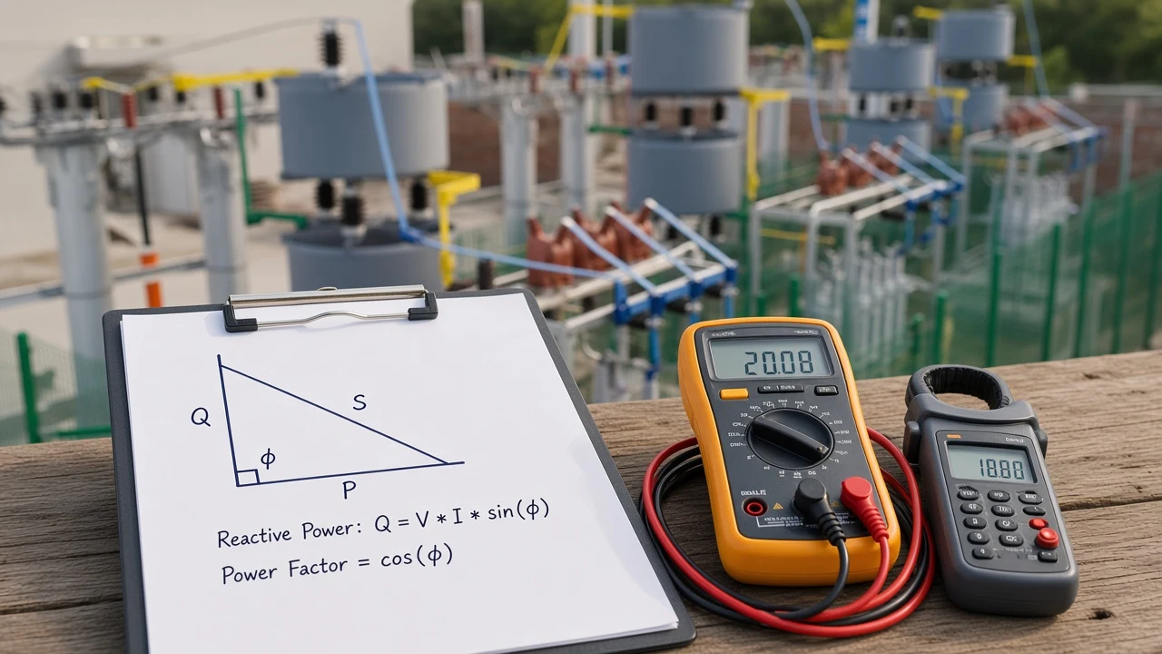
Calculate Reactive Power from Power Factor
Use Q = P × tan(arccos PF) with consistent units when you need to calculate reactive power from power factor. That path is the fastest when a board already shows kilowatts and a decimal PF.
Steps:
- Confirm PF is a decimal between 0 and 1 (0.80, not “80” alone).
- Find the phase angle φ = arccos(PF).
- Compute Q = P × tan(φ), or equivalently Q = P × √(1 − PF²) / PF for lagging displacement PF under sinusoidal assumptions.
Educational arithmetic from stated inputs: if P = 100 kW and PF = 0.80, then φ ≈ 36.87° and Q = 100 × tan(36.87°) = 75 kvar.
The same board can cross-check with the triangle. If S = 125 kVA and P = 100 kW, Q = √(125² − 100²) = 75 kvar.
PF itself is a separate ratio (P/S). When you need the PF calculation procedure rather than Q, use the sibling guide on how to calculate power factor.
Single-Phase Reactive Power Calculation Steps
Use simultaneous RMS voltage, current, and phase—or simultaneous P and S—on single-phase boards. Do not multiply V × I and call the product watts before you extract Q.
Path A — from V, I, and φ:
- Measure Vrms and Irms at the same point and interval.
- Measure or compute φ from a power analyzer (or from a known PF via φ = arccos PF).
- Compute Q = V × I × sinφ (VAR), then divide by 1,000 for kvar if needed.
Path B — from P and S:
- Measure real power P with a wattmeter or analyzer channel.
- Form S = Vrms × Irms (VA), or use a metered kVA channel.
- Compute Q = √(S² − P²).
Educational single-phase pattern from stated inputs: 480 V, 100 A, PF = 0.80 gives S = 480 × 100 = 48,000 VA, P = 38,400 W, and Q = 48,000 × √(1 − 0.80²) = 28,800 VAR (28.8 kvar).
Vrms × Irms is apparent power, not automatically real power. Without a true P channel, the triangle identity cannot invent Q.
Three-Phase Reactive Power with √3
For balanced systems use √3 · V_LL · I_L · sinφ. Under balanced sinusoidal assumptions, that line-to-line identity is the plant default for how to calculate reactive power in 3 phase.
Q (VAR) = √3 × V_LL × I_L × sinφ
Q (kvar) = √3 × V_LL × I_L × sinφ ÷ 1,000
√3 is about 1.732. Omitting it under those assumptions understates Q the same way it understates three-phase S.
You can also stay on the triangle after totals are known: Q = √(S² − P²) using three-phase total P and total S, or Q = P × tan(arccos PF) using three-phase total P and a compatible PF.
Educational balanced pattern from stated inputs: V_LL = 400 V, I_L = 100 A, PF = 0.87. Then S ≈ √3 × 400 × 100 ≈ 69,282 VA, P ≈ 60,275 W, and Q ≈ 34,160 VAR (about 34.2 kvar in magnitude).
For a deeper three-phase formula worksheet—line vs phase forms and more worked identities—see the live sibling reactive power formula in 3 phase. This page keeps the balanced √3 path and then moves on to capacitor kvar and field mistakes.
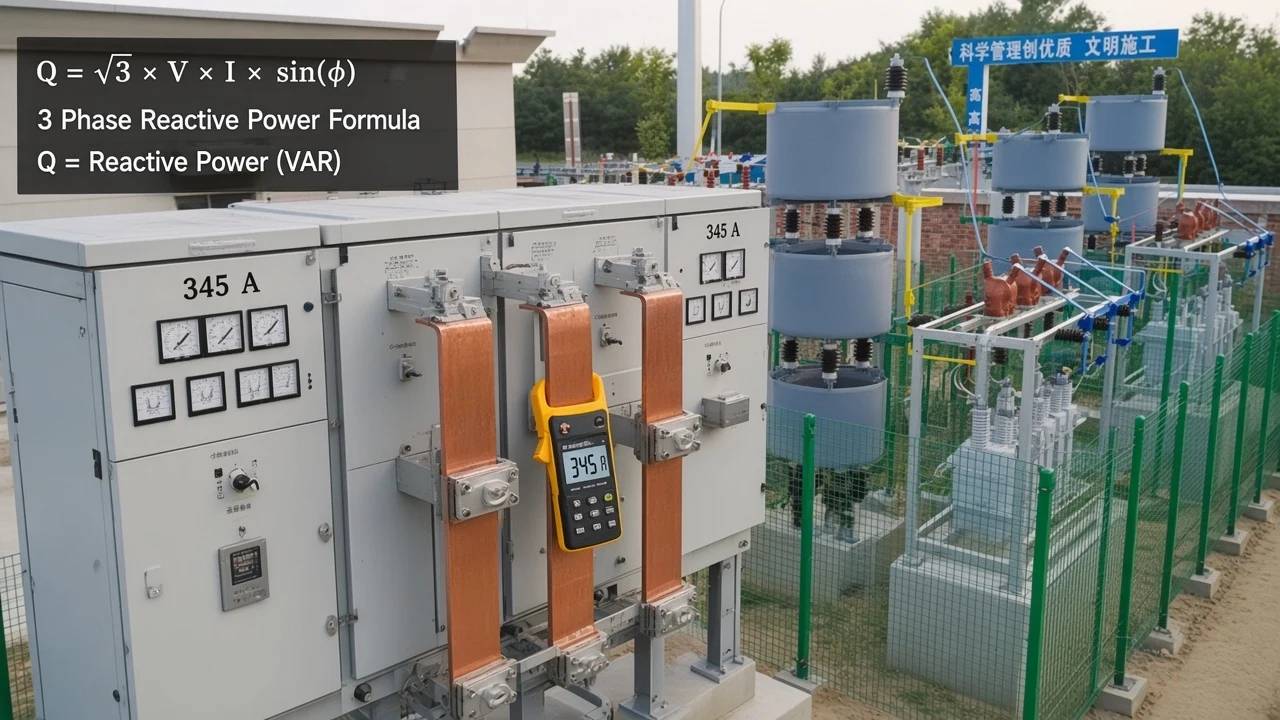
Unbalanced or heavily distorted feeders need multi-channel analyzer totals. One CT on one phase is not a free pass to a plant-wide kvar number.
Capacitor Reactive Power from C, f, and V²
Qc ≈ 2πfCV²; output scales with V². When you start from capacitance rather than from a load PF, that identity is how to calculate reactive power of capacitor units at the applied voltage.
For a capacitor with capacitance C (farads), frequency f (hertz), and RMS voltage V across the capacitor:
Qc = 2π f C V² (VAR)
Convert µF to F by multiplying by 10⁻⁶. Divide VAR by 1,000 for kvar. For three-phase banks, use line voltage for a delta connection and phase voltage for a star connection—mixing those voltages is a common sizing error.
Educational arithmetic from stated inputs: C = 25 µF, V = 400 V, f = 50 Hz gives Qc = 2π × 50 × 25×10⁻⁶ × 400² ≈ 1,257 VAR ≈ 1.26 kvar on a single-phase basis.
Nameplate kvar assumes rated voltage. At constant C and f, delivered kvar scales roughly with (V_op / V_rated)².
Educational voltage check from stated inputs: a 1,000 kvar bank rated at 13.8 kV supplies about 1,000 × (13.2/13.8)² ≈ 915 kvar if the bus runs at 13.2 kV with frequency unchanged.
University lessons also note that industrial catalogs often name capacitors in kvar at a stated voltage, and the sign opposite inductive load Q when you net the bank against motors (Louisville EE220 Lesson 12).
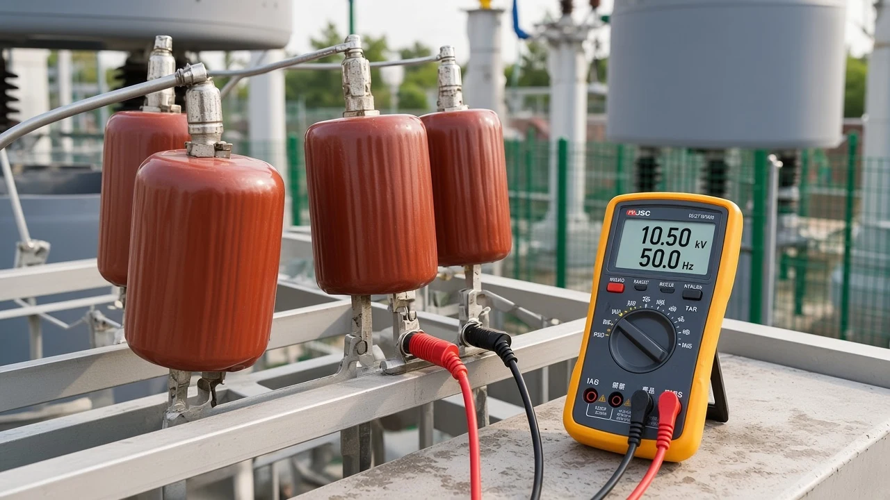
Important: Capacitor kvar is not fixed once you leave nameplate voltage. If the bus is depressed, shunt capacitors deliver less VAR roughly with the square of voltage—so a bank sized only from a PF table can under-support a weak bus.
Required capacitor kvar to move a load from PF₁ to a target PF₂ is a related next step: Qc = P × (tan φ₁ − tan φ₂). When you need that bank-sizing path, open how to calculate kvar for capacitor bank after this page has locked existing Q.
Field Mistakes That Skew a Reactive Power Calculation
Do not treat V×I as watts; net signed Q for mixed loads. Most wrong kvar numbers come from bad inputs, not from a wrong square-root button.
Common failure modes:
- Calling Vrms × Irms “watts,” then feeding that fake P into √(S² − P²).
- Mixing kW with VA (forgetting the 1,000) so Q looks absurdly large or small.
- Using percent PF (80) instead of decimal PF (0.80) inside tan(arccos PF).
- Applying a single √(S_total² − P_total²) when some branches lead and others lag—compute signed Q per group, then net.
- Ignoring harmonics: capacitors mainly correct displacement Q; distortion needs a separate diagnosis.
From the field: Plant techs still paste RMS volts times amps into a kvar spreadsheet and wonder why the triangle does not close. The same EEVblog beginners thread that debunks that habit for power factor also applies here: without a wattmeter-style real-power channel, √(S² − P²) has nothing honest to stand on—EEVblog thread on electronics math and power factor.
If you still need the physical meaning of Q in an RL circuit rather than the arithmetic, see what reactive power represents in an AC RL circuit.
Which HYTBB Fit After You Calculate Required kvar
MV/HV shunt banks are selected from required kvar and voltage once Q is known. After the arithmetic, the hardware question is which compensation package matches system voltage, harmonics, and capacity—not which formula to run again.
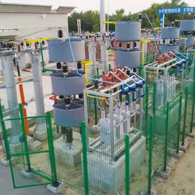
The HYTBB Series High-Voltage Reactive Power Compensation Device – Outdoor Frame Type provides shunt capacitor compensation for substations and industrial distribution systems. Reactor ratio, protection method, connection form, and fixed or automatic switching mode are selected from the system voltage, harmonic conditions, and required capacity.
Published ratings include 6–35 kV system voltage and 50–60 Hz frequency. Published capacity ranges include 150–10,000 kvar at 10 kV and below and 600–20,000 kvar at 35 kV. Single capacitor unit capacity is published as 50–500 kvar.
| Parameter | Published range |
|---|---|
| System voltage | 6–35 kV |
| Rated frequency | 50–60 Hz |
| Rated capacity (≤10 kV) | 150–10,000 kvar |
| Rated capacity (35 kV) | 600–20,000 kvar |
| Single capacitor unit | 50–500 kvar |
Browse the full High Voltage Power Factor Compensation Series when dynamic TSC/SVG options may fit fluctuating nonlinear loads better than a fixed or stepped outdoor frame. Do not invent listing, savings, or payback numbers beyond what the product page prints.
FAQ
How do you calculate reactive power?
Use the path that matches your inputs: Q = V × I × sinφ, Q = √(S² − P²), or Q = P × tan(arccos PF). Keep P, S, V, and I from the same interval, and convert to kvar when you work in kilounits.
How do I calculate kVAR from kW and power factor?
Convert PF to a decimal, then Q (kvar) = P (kW) × tan(arccos PF). Educational check: 100 kW at 0.80 PF gives 75 kvar.
What is the three-phase reactive power formula?
For balanced sinusoidal systems, Q = √3 × V_LL × I_L × sinφ, or use three-phase totals in Q = √(S² − P²) or Q = P × tan(arccos PF). See also the sibling reactive power formula in 3 phase for more formula detail.
How do I find kvar from a capacitor’s µF rating?
Use Qc = 2π f C V² with V across the capacitor, then scale for star vs delta voltage correctly. Remember delivered kvar falls roughly with V² if the bus is below nameplate voltage.
What unit is reactive power measured in?
Reactive power uses var (volt-ampere reactive). Plant work usually reports kvar or Mvar. It is not interchangeable with watts or with VA, even when the numeric magnitudes look similar.
Can I calculate Q from apparent and real power only?
Yes, when the sinusoidal power triangle holds for that interval: Q = √(S² − P²). You still need honest P and S—do not invent watts from a clamp-only amp reading.
Why does capacitor kvar change with voltage?
At fixed C and f, Qc ∝ V². A bank rated 1,000 kvar at 13.8 kV delivers about 915 kvar at 13.2 kV in the educational voltage-squared check above.
After I calculate Q, how do I size a capacitor bank for a target PF?
Existing Q tells you the inductive demand. The kvar to install for a target PF uses Qc = P × (tan φ₁ − tan φ₂). Follow how to calculate kvar for capacitor bank for that sizing spine.