
 Zhejiang Hongyan Electric Co., Ltd.






































To define power factor in electrical engineering, use the ratio of real power to apparent power—how much of the supplied volt-amperes is converted into useful work. The sections below lock that textbook identity (P/S, and cos φ when waves are sinusoidal), separate displacement from true power factor, name lagging/leading/unity as type labels, explain why plants care about capacity, losses, and utility charges, and show where a low-voltage static compensation cabinet that switches on measured power factor fits after the definition is clear.
If you only keep one line, keep this: PF = P / S. Cos φ is the clean-sine form of the same idea—not a rival definition.

The Electrical Engineering Definition of Power Factor
Power factor is real power divided by apparent power. In electrical engineering that identity is written PF = P / S.
Real power (active power) is the average of the instantaneous product of voltage and current—the watts that heat, move, and light. Apparent power is the product of RMS voltage and RMS current: the volt-amperes the source, feeder, and transformer must be able to deliver.
Encyclopedia language matches the same head definition: in electrical engineering, power factor is the ratio of the real power absorbed by the load to the apparent power flowing in the circuit (Wikipedia — Power factor). When that ratio is less than one, more current flows than would be required to transfer the same real power alone.
| Quantity | Symbol | Unit | Role in the definition |
|---|---|---|---|
| Real (active) power | P | W / kW | Useful work; numerator of PF |
| Reactive power | Q | VAR / kVAR | Field energy exchange; grows the triangle (brief here) |
| Apparent power | S | VA / kVA | Vrms × Irms; denominator of PF |
On the power triangle, S² = P² + Q² under sinusoidal assumptions, and PF = P / S = cos φ (Electronics Tutorials — Power triangle). Reactive power is only sketched here so the ratio makes sense; a dedicated active-versus-reactive definition belongs on its own page—not this one.
So a power factor definition for plant work is not “how efficient the motor feels.” It is a measured fraction of volt-amperes that become real work at the metering point.
Cos φ and the Sinusoidal Case
For sinusoidal voltage and current, power factor equals cos φ. University AC teaching derives average power as Pave = Irms Vrms cos φ and names cos φ the power factor (OpenStax — Power in an AC Circuit).
Open engineering notes write the same link as PF = P / S = cos(φ) (OERTX — AC Circuit Analysis, Power Factor). Phase angle φ is the angle between sinusoidal voltage and current.
When φ = 0°, voltage and current are in phase and PF = 1. When φ approaches ±90°, average real power collapses toward zero while apparent power can remain large—purely reactive limiting cases that still force the source to carry current.
Treat cos φ as the sinusoidal case of the P/S definition, not a second competing formula. If the waves leave the clean-sine world, keep reading the next section before you trust a cosine-only badge on a meter.

Displacement Power Factor vs True Power Factor
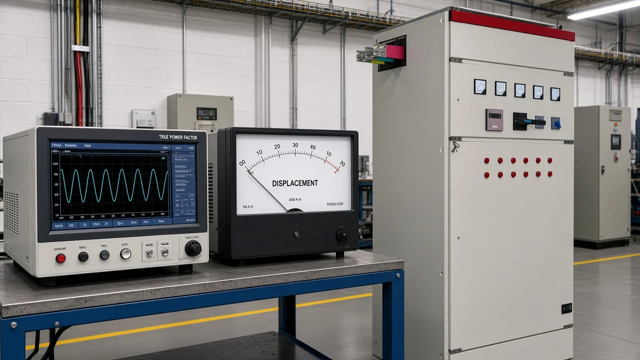
Displacement power factor ignores harmonics; true power factor includes them. Displacement power factor (DPF) is the cosine of the phase angle between the fundamental-frequency voltage and current.
True power factor is real power divided by total RMS apparent power over the same window—so harmonic current that raises RMS amperes without adding much real power pulls true PF down while DPF can stay high (Power Monitors — PF vs DPF). On undistorted sine waves the two numbers match.
Practical use on plant buses:
- Use displacement power factor when you are judging fundamental reactive power and capacitor-bank effectiveness.
- Use true PF when you care about overall feeder and transformer burden under distortion.
That split is why two meters—or two channels on one analyzer—can disagree without either being “broken.” It is also why a capacitor-only project can improve DPF while true PF stays soft if harmonics dominate the VA.
Lagging, Leading, and Unity as Type Labels
Lagging means current lags voltage; leading means current leads voltage; unity means they are in phase. These labels classify the sign of the phase relationship after you already have the P/S definition—they are not a second definition of power factor.
| Label | Voltage–current relationship | Typical plant cause |
|---|---|---|
| Unity power factor | In phase (φ ≈ 0°) | Near-resistive or well-corrected bus |
| Lagging | Current behind voltage | Motors, transformers, inductive loads |
| Leading power factor | Current ahead of voltage | Capacitive circuits or over-applied capacitors |
Open course notes use the same naming and note that industrial equipment such as motors and transformers typically presents a lagging power factor (OERTX). For a full taxonomy walk-through of the three types before buying correction, use the dedicated 3 types of power factor guide. Here the labels only keep the EE definition oriented on a plant bus.
Why Electrical Engineers Care About Power Factor
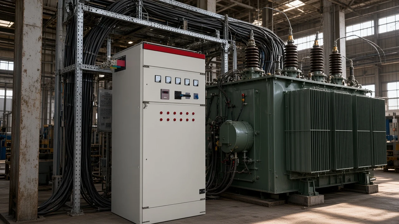
Low power factor raises current, consumes feeder and transformer capacity, and increases resistive losses for the same real load. For a fixed kilowatt demand, a lower PF means a larger kilovolt-ampere requirement—so conductors, switchgear, and transformers must be sized for more amperes than the process watts alone suggest (OERTX; DOE industrial power-factor cost sheet).
That is the engineering reason first: capacity and I²R heating. Billing is second and local.
DOE industrial guidance notes that many utilities apply additional charges when power factor falls below a tariff threshold (0.95 is cited as a common example)—but the trigger, formula, and measurement point are rate-schedule specific, not a universal law (DOE fact sheet).
Important: Treat low power factor as a current and capacity problem first. Utility surcharges may apply, but only where your tariff says so—read the rate schedule instead of assuming a single national penalty.
None of that requires inventing a payback spreadsheet. The definition-level takeaway is enough: poor PF wastes ampacity before it wastes money.
Reading Power Factor on Plant Meters and Reports
Decimal power factor on a report is P/S from the stated inputs on that report. Write it as 0.80 or 80%—same ratio.
These educational examples use stated inputs only; they are not logged readings from a named plant.
| Example | Stated inputs | Result | How to read it |
|---|---|---|---|
| A — DOE triangle style | 100 kW and 142 kVA | PF = 0.70 (70%) | Seventy percent of apparent power is real work (DOE) |
| B — eighty percent | 80 kW and 100 kVA | PF = 0.80 (80%) | Common spoken “0.8 power factor” |
| C — target language | Meter shows 0.95 | PF = 0.95 (95%) | Often discussed as a correction target; not a universal legal limit |
Signed or “negative” PF readings on analyzers usually encode direction of real power or a lead/lag sign convention—not a second physical magnitude outside 0–1 for ordinary load-side ratios. When a meter also prints DPF and true PF, compare them before you blame the definition. Community meter threads make the same literacy point: separate VA from watts before you trust a power-factor number (EEVblog — Power factor explained).
For the arithmetic path from measured kW and kVA to PF, use how to calculate power factor. For a shorter AC-circuit intro framing, see what is power factor in an AC circuit.
Where LV Static Compensation Fits After the Definition
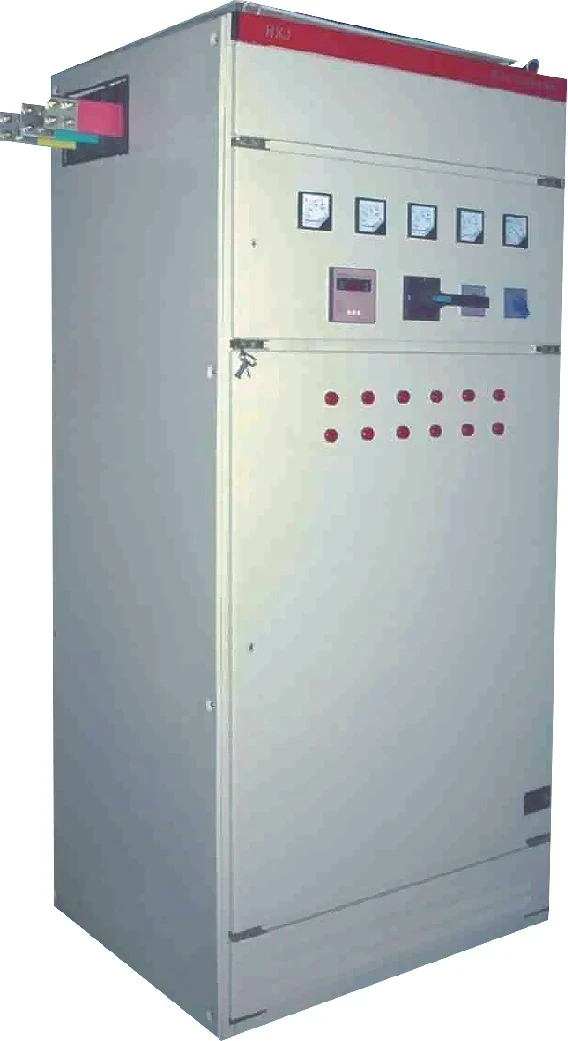
After you can define PF and recognize lagging, relatively steady inductive demand, a low-voltage static bank that switches capacitor groups from measured reactive demand or power factor is a logical next hardware step.
For that path, CHYN publishes the HYTBBJ Series Low-Voltage Static Reactive Power Compensation System. The cabinet stages capacitor groups from measured reactive demand or power factor, offers manual or automatic PF/reactive-current modes, and displays three-phase voltage, current, and power factor while compensation runs.
The model-code table on the product page prints a 0.4 kV system voltage example. Switching delay is adjustable from 0–120 s, with a special fast mode listed at ≤1 s.
Choose the static path when loads are relatively steady. Large swing profiles belong on a dynamic series discussion; motor-end correction may use end-point devices.
Do not add capacitors to “fix” an already-leading bus. Browse the low-voltage power factor compensation series (the LV PF series hub) for the family map after the definition is settled.
FAQ
What is the definition of power factor in electrical engineering?
Power factor is the ratio of real power to apparent power (PF = P / S). It states what fraction of the supplied volt-amperes becomes useful work at the metering point (Wikipedia — Power factor).
Is power factor the same as cos φ?
Under sinusoidal voltage and current, yes—PF equals cos φ. That is the engineering teaching form of average AC power (OpenStax). Under distortion, prefer true PF = P / S from RMS quantities.
What is displacement power factor vs true power factor?
Displacement power factor uses only the fundamental phase angle. True power factor divides real power by total RMS apparent power, so harmonics that inflate RMS current lower true PF (Power Monitors — PF vs DPF).
What are lagging, leading, and unity power factor?
Lagging: current lags voltage (typical inductive loads). Leading: current leads voltage (capacitive). Unity: in phase, PF = 1.
These are type labels on top of the P/S definition (OERTX).
Why does power factor matter for plant capacity and losses?
For the same real power, a lower PF means higher current and larger apparent power. That consumes feeder and transformer capacity and raises I²R losses (OERTX; DOE).
What does a power factor of 0.8 mean?
It means 80% of apparent power is real work—for example, 80 kW with 100 kVA gives PF = 0.80. The DOE educational triangle uses 100 kW / 142 kVA ≈ 0.70 as a similar reading exercise (DOE).
Do utilities always penalize low power factor?
No. Some utilities apply additional charges below a tariff threshold; DOE cites 0.95 as a common example. Always verify the rate schedule for your site (DOE).
After I understand the definition, what LV equipment fits lagging steady loads?
Calculate from measured kW and kVA with the how to calculate power factor guide. Classify lagging/leading/unity with 3 types of power factor. For steady lagging inductive LV loads, review the HYTBBJ Series after the definition is clear.
References
- Wikipedia — Power factor
- OpenStax University Physics Volume 2 — 15.4 Power in an AC Circuit
- OERTX — Chapter 14 AC Circuit Analysis (Power Factor)
- U.S. DOE — Reducing Power Factor Cost (mc60405)
- Power Monitors — Power Factor vs Displacement Power Factor
- Electronics Tutorials — Power Triangle and Power Factor
- EEVblog Forum — Power factor explained