
 Zhejiang Hongyan Electric Co., Ltd.






































To convert power factor to phase angle, take the inverse cosine of the decimal power factor with the calculator in degrees—φ = arccos(PF)—then label the result lagging or leading from the meter or load type, because arccos returns magnitude only. You will get the cosine relationship, a step checklist, worked examples with a lookup table, the reverse conversion, sign convention, and when a “true” power factor under distortion is not a single clean angle.
Power Factor and Phase Angle: The Cosine Link
For sinusoidal voltage and current, power factor equals the cosine of the phase angle φ between them: PF = cos φ. Arccos / cos⁻¹ is the operator that recovers that angle from a known PF.
That single identity is why a nameplate or meter PF can become an angle for a power-triangle sketch. Real power P sits on one leg of the triangle, reactive power Q on the other, and apparent power S on the hypotenuse. The angle between P and S is the same φ that appears between voltage and current on a phasor diagram (Electronics Tutorials power triangle; Wikipedia on power factor).
Two extreme checks keep the intuition honest:
- Unity power factor (PF = 1) means φ = 0°—voltage and current are in phase.
- A power factor of 0 means φ = 90°—the exchange is entirely reactive.
Between those ends, a higher PF means a smaller angle. A lower PF means a wider angle and more reactive burden for the same real work.
For what power factor is in an AC circuit in broader language, see what is power factor in an AC circuit. For unity / lagging / leading types without repeating that taxonomy here, see 3 types of power factor.
How to Convert Power Factor to Phase Angle Step by Step
Phase-angle magnitude is φ = arccos(PF) when PF is a decimal between 0 and 1 and the calculator is in degrees mode. That arccos power factor step is the whole forward conversion in one line.
Follow these steps when you need power factor to phase angle for a diagram or controller note:
- Read PF as a decimal. If the display shows 85% or 0.85 pf, use 0.85—not 85.
- Confirm the calculator is in DEG, not RAD. Radians turn a correct arccos into a number that looks nothing like plant degrees.
- Compute φ = arccos(PF) or cos⁻¹(PF).
- Round sensibly for the job (often one decimal place for sketches; keep more digits if you will reverse-check).
- Assign lagging or leading from the meter’s LAG/LEAD label, VAR sign, or known load type—arccos alone does not choose the side.
- Spot-check: cos(φ) should return approximately the original PF.
Electricians asking for “the formula” usually land on the same identity: phase angle = cos⁻¹(PF). Under sinusoids you can also write φ = arccos(P/S) when you already have watts and volt-amperes (Omni Calculator power factor article).

| Direction | Formula | Calculator habit |
|---|---|---|
| PF → phase angle | φ = arccos(PF) | DEG mode; PF as 0–1 decimal |
| Phase angle → PF | PF = cos φ | Same angle unit you used for φ |
| From powers | φ = arccos(P/S) | P in W (or kW), S in VA (or kVA), same scale |
| Sign / side | Not from arccos | Read LAG/LEAD, Q sign, or load type |
If you still need to build PF from meter kW and kVA first, use how to calculate power factor—then return here for the angle.
Worked Examples and a PF-to-Degrees Lookup Table
Common plant values convert cleanly: PF 0.80 → about 36.87°; PF 0.90 → about 25.84°; PF 0.95 → about 18.19°.
Example A — nameplate PF. A motor nameplate lists PF = 0.85. You need φ for a power-triangle sketch:
φ = arccos(0.85) ≈ 31.79°.
Label the angle lagging if the motor is a conventional induction machine drawing lagging current. The 31.79° figure is educational arithmetic from the stated nameplate input, not a logged plant measurement.
Example B — from P and S. A feeder shows P = 1,000 W and S = 1,250 VA at the same interval:
PF = 1,000 / 1,250 = 0.80
φ = arccos(0.80) ≈ 36.87°.
Example C — reverse check. Target angle 18.19° on a sketch:
PF = cos(18.19°) ≈ 0.95.
The table below is a quick phase angle from power factor lookup for sinusoidal displacement. Values are educational, computed with the inverse cosine in degrees.
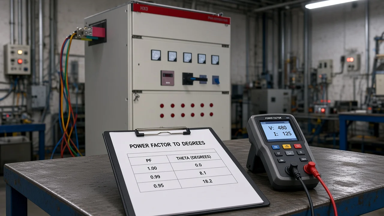
| Power factor (decimal) | Phase-angle magnitude φ (°) |
|---|---|
| 1.00 | 0.00 |
| 0.98 | 11.48 |
| 0.95 | 18.19 |
| 0.90 | 25.84 |
| 0.85 | 31.79 |
| 0.80 | 36.87 |
| 0.75 | 41.41 |
| 0.70 | 45.57 |
| 0.60 | 53.13 |
| 0.50 | 60.00 |
Convert Phase Angle Back to Power Factor
To reverse the conversion, compute PF = cos φ with the same degree (or radian) unit you used for the angle.
That is the other half of the cosine link stated in textbooks and calculators: if φ is 36.87°, PF = cos(36.87°) ≈ 0.80 (Omni Calculator; Electronics Tutorials).
Practical habits:
- Keep DEG mode when φ is written in degrees on a one-line diagram.
- If a controller setpoint is entered as a target PF (for example 0.95), you already have the cosine form; convert to angle only when the drawing or teaching note needs degrees.
- After any hand calculation, reverse once: arccos then cos, or cos then arccos, should close within rounding error.
Do not confuse the phase angle with the PF number itself. A PF of 0.8 is not “80 degrees,” and 36.87° is not “0.3687 PF.”
Lagging vs Leading: What Arccos Does Not Tell You
Arccos returns the magnitude of the phase angle; lagging versus leading is a separate label from load type, VAR flow, or the meter’s lead/lag indication.
Cosine is an even function: cos(+φ) = cos(−φ). A lagging inductive load and a leading capacitive load can share the same unsigned PF and the same arccos result while their reactive powers have opposite signs (Wikipedia power factor — lagging and leading).
Important: After you convert power factor to phase angle, do not invent the sign from arccos alone. Read LAG/LEAD on the instrument, the signed reactive power, or a verified current-versus-voltage check before you call the angle lagging or leading — Wikipedia on power factor.
Plant shorthand:
- Inductive loads (motors, transformers) typically present a Lagging PF—current lags voltage.
- Capacitive loads (shunt banks, some cable-heavy lightly loaded feeders) typically present a Leading PF—current leads voltage.
For a full plant checklist on lead versus lag diagnosis, use how to know if power factor is leading or lagging—this page only keeps the conversion-side warning.

When Meters Report PF vs Degrees (and Distortion Limits)
Many plant meters report dimensionless PF; analyzers and teaching tools may also show degrees—both describe the same sinusoidal relationship when the reading is displacement power factor.
Under clean sinusoids, a meter that shows PF = 0.90 and a display that shows φ ≈ 25.8° are two languages for one angle. Controllers for automatic power-factor correction often regulate on PF or reactive current rather than on a degrees setpoint; the conversion still helps humans draw triangles and compare nameplates.
The hard limit: arccos of true power factor is not a single clean displacement angle when voltage or current is heavily distorted. True PF vs cos φ matters here: power factor is always P/S, while cos φ equals that ratio only for sinusoidal waveforms. With non-linear loads—VFDs, rectifiers, many electronic supplies—the total PF includes distortion as well as displacement, so “φ = arccos(true PF)” mixes effects that capacitors alone cannot fully undo (Electronics Stack Exchange discussion of PF vs cos φ).
Field habit when harmonics are obvious:
- Prefer a meter that reports displacement PF or fundamental phase separately if you need a power-triangle angle.
- Treat arccos(true PF) as a rough magnitude only, not as a precise phasor for settings.
- Keep simultaneous P and S readings on the same interval before converting.
Which HYTBBJ Fit When You Already Know φ and PF
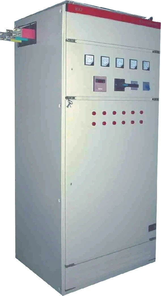
Once φ and PF are known for diagrams or target settings, a low-voltage static bank that switches on measured power factor is a practical next step for relatively steady inductive loads.
HYTBBJ is CHYN’s low-voltage static reactive power compensation system: it stages capacitor groups from measured reactive demand or power factor. It supports power-factor (reactive current) control in manual and automatic modes, and it monitors three-phase voltage, current, power factor, and compensation status.
Model coding on the product page includes a 0.4 kV system voltage example. The series is positioned for manufacturing, buildings, and public facilities where inductive reactive demand is relatively stable.
Browse the hub for related LV options: Low Voltage Power Factor Compensation Series. Highly swinging reactive demand may need a dynamic series instead of a static bank.
Extra capacitance into a net leading condition pushes the wrong way. Published claims here stay limited to printed product wording—no UL/NEC listings, SKUs, kilowatt-hour savings, or payback periods.
FAQ
How do I convert power factor to phase angle?
Use φ = arccos(PF) with PF as a decimal between 0 and 1 and the calculator in degrees. Then assign lagging or leading from the meter or load type.
What is the phase angle for a 0.8 power factor?
arccos(0.8) ≈ 36.87°. That is the magnitude only; label lagging or leading separately.
How do I convert phase angle back to power factor?
Compute PF = cos φ with matching units (degrees with DEG mode). Example: cos(36.87°) ≈ 0.80.
Does arccos tell me lagging or leading?
No. Cosine loses the sign. Use LAG/LEAD indication, reactive-power sign, or a current-versus-voltage check.
Should my calculator be in degrees or radians?
Use degrees when you want plant-style ° on diagrams. Radians return a different numeric scale and are a common conversion mistake.
Is power factor always equal to cos φ?
For sinusoidal voltage and current, yes for displacement. With distorted waveforms, true PF = P/S is not generally cos of one clean phase angle.
What is the phase angle at unity power factor?
Unity PF (1.0) corresponds to φ = 0°.
Why do some meters show degrees and others show PF?
They are two presentations of the same sinusoidal relationship. Controllers often regulate on PF; drawings often need degrees—convert with arccos or cos as needed.