
 Zhejiang Hongyan Electric Co., Ltd.






































An externally fused capacitor bank uses a separate fuse outside each capacitor unit to disconnect that unit when a fault develops. This is different from internal element fusing and from a fuseless arrangement. For a buyer, the decisive questions are what a fuse removes, how the remaining units are stressed afterward, and how the bank protection responds. A visible fuse is useful for fault location, but it does not replace an engineered protection study. This guide focuses on medium- and high-voltage shunt banks, rather than small electronic capacitors or a complete bank-sizing calculation.
What the external fuse protects
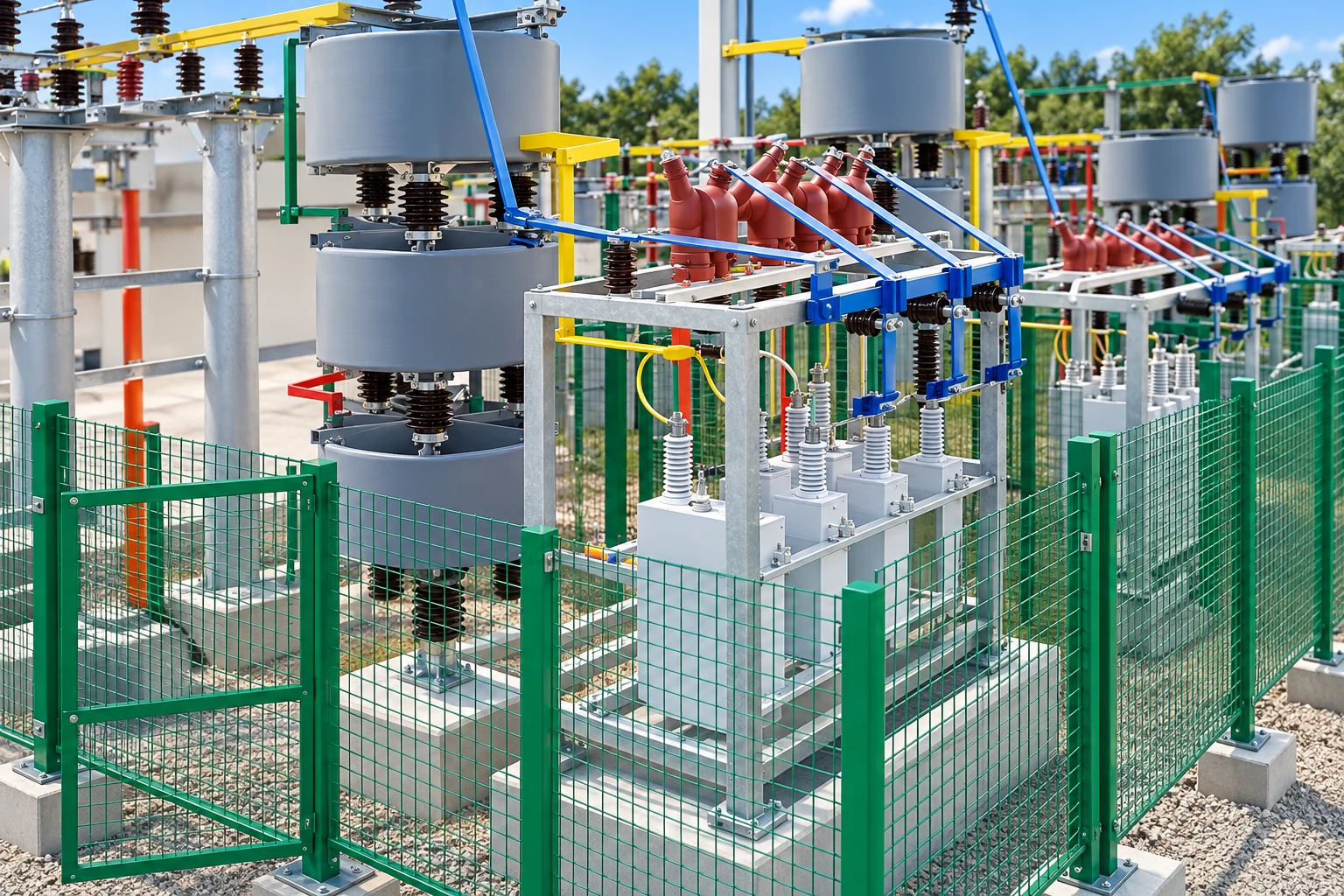
A capacitor can contains multiple dielectric elements connected into an internal network. The complete can is the capacitor unit. In a conventional individually externally fused arrangement, the external fuse is in series with that unit. When it clears a qualifying fault, the entire unit leaves service. The surrounding rack can remain physically intact while its electrical balance changes.
Do not confuse this unit fuse with an incoming bank fuse. A bank-level fuse may disconnect a phase or a larger assembly; it does not necessarily provide selective isolation of each can. Before comparing quotations, mark the unit boundary and fuse location on the supplier's drawing. Ask the supplier to identify whether protection is individual, grouped, or bank level.
The IEEE 1036 shunt capacitor application guide addresses application, protection, and equipment ratings for 50/60 Hz capacitors rated 2400 Vac and above. Its published scope describes general guidance that supplements manufacturer recommendations. A statement that a proposal “follows IEEE” is therefore not a substitute for drawings and a project-specific coordination report.
External, internal, and fuseless arrangements: the service difference
| Arrangement | What changes after a dielectric fault | What the maintenance team needs |
|---|---|---|
| Individually externally fused | A clearing unit fuse disconnects the complete capacitor can. | Unit identification, approved fuse replacement, capacitance records, and bank unbalance assessment. |
| Internally fused | An internal fuse disconnects an individual element or protected internal section, according to construction. | Capacitance testing and protection records; a healthy-looking case does not prove unchanged capacitance. |
| Fuseless | The design accommodates specified element failures without an individual fuse clearing each unit. | Protection matched to the series-parallel arrangement and a documented method of locating affected units. |
This table compares the isolation principle, not a universal ranking of safety or reliability. The IEEE capacitor bank overview describes series-parallel configurations and the role of unbalance protection. Selection still requires the actual unit construction, bank arrangement, and manufacturer data. Do not transfer another installation’s fuse ratings or protection limits to your bank.
Use the existing guides to internally fused capacitor units and fuseless capacitor banks when comparing those alternatives in detail. Here the focus stays on external unit isolation and the documents needed to make that choice defensible.
Why losing one can can stress the remaining capacitors
In a bank with several series groups, each group may contain parallel capacitor units. Removing one unit reduces that group's capacitance. Because series groups share charge in the simplified steady-state model, the lower-capacitance group takes a larger share of the applied voltage. The remaining units in that group can therefore see increased voltage even though total bank current has fallen.
Consider an intentionally simplified example: two initially identical series groups, each containing ten identical parallel units, supplied by a fixed sinusoidal voltage. Each group initially receives half the total voltage. If one complete unit is disconnected from one group, the affected group's capacitance becomes 0.9 times the other group's capacitance.
For two ideal series capacitors, the affected group's voltage share is Chealthy / (Caffected + Chealthy). The new share is therefore 1 / 1.9 = 0.5263 of total voltage, compared with 0.5 initially: a 5.26% increase relative to that group's original voltage. This is an educational calculation, not a permissible operating limit or relay setting.
A real three-phase bank can have neutral displacement, unequal tolerances, multiple series groups, reactors, harmonics, and changing bus voltage. Those effects require the actual network model. In a single series-group arrangement, losing a parallel unit changes kvar and phase balance without the same two-group redistribution mechanism. The connection diagram determines which failure model applies.
Specify a fuse coordination study, not just an ampere rating
Normal capacitor current is only the starting point. For a capacitor unit, use its own voltage and reactive-power rating, not the entire bank's rating. The designer must then assess normal operating variations, harmonic current, energization duty, available fault current, and the unit's withstand characteristics. A generic multiplier copied from another project cannot establish coordination.
Ask for time-current curves showing the proposed fuse's minimum-melting and total-clearing behavior against the applicable capacitor damage or case-rupture data. The review must distinguish a fault the unit fuse should clear from an external fault the bank's upstream protection should remove. Check the voltage rating and interrupting capability as well as the continuous current rating.
Stored energy from parallel capacitors matters because a faulted can can receive discharge energy from neighboring units. Nearby switched banks may add another duty. More cans in parallel are therefore not just a mechanical expansion. The supplier should show the parallel-energy assessment and explain why the chosen fuse technology is suitable for the complete arrangement.
For an expulsion fuse, include the required operating space and discharge path in the layout review. For a current-limiting fuse, require the specific manufacturer's application and coordination data. Neither option should be substituted solely because the replacement has the same printed current rating. Keep the approved manufacturer, model, and revision in the spare-parts schedule.
The bank still needs unbalance and system protection
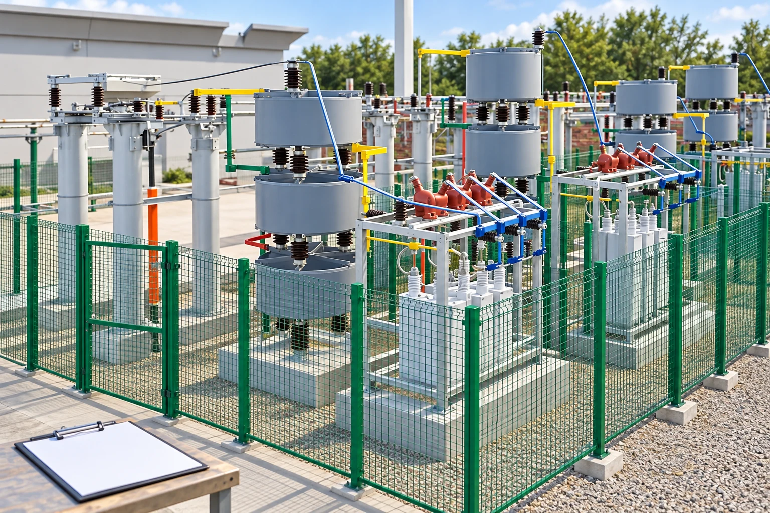
External unit fuses and bank relays solve different problems. A fuse provides local isolation. Unbalance protection detects the change in the capacitor network and supports an alarm or trip decision before the remaining equipment is overstressed. Phase overcurrent alone may not detect a developing loss of capacitance with sufficient sensitivity.
The sensing scheme depends on grounded or ungrounded connection, single or double wye, instrument-transformer placement, and the number of series groups. A useful study models the healthy baseline, natural manufacturing tolerances, the first relevant failure, and subsequent failures. It also explains how system voltage unbalance is distinguished from internal bank unbalance.
Specify the response to each condition: alarm, immediate trip, time-delayed trip, and close blocking. Include loss of sensing, relay supply failure, and breaker failure where required by the project. Do not assume that every single fuse operation permits continued service. For a deeper explanation of detection methods, see capacitor bank unbalance protection.
What to do after an operated external fuse is reported
First preserve the evidence: time stamp, bank step, phase, unit position, relay event, bus voltage, recent switching, and any associated alarms. Avoid repeated closing attempts. An open fuse can indicate a capacitor defect, external flashover, unsuitable duty, or a coordination issue; replacing it without finding the cause can erase useful evidence and repeat the failure.
Inspection and testing belong to qualified personnel using the site's isolation and stored-energy procedure. A disconnected bank is not automatically safe to touch. The U.S. OSHA electrical work-practice rule addresses isolation, verification, and release of hazardous stored energy. Apply the governing local rules and the equipment manufacturer's discharge and grounding instructions.
After safe isolation, compare the affected unit with its documented baseline and inspect the approved components and connections. Record capacitance with the specified test method, identify physical damage or contamination, and verify the replacement's voltage, kvar, construction, and matching requirements. Return-to-service approval should include restoration of the required protection checks and an updated unit map.
When external fusing is a practical procurement choice
An externally fused arrangement may suit a project where individual unit identification, accessible replacement, an established maintenance practice, and verified coordination are priorities. It may be less attractive where enclosure space, environmental exposure, spare-parts logistics, or protection sensitivity makes another arrangement preferable. The decision belongs to the complete system design rather than to the fuse alone.
CHYN's HYTBB outdoor frame compensation equipment provides relevant product context for a packaged shunt-bank discussion. Its product page does not establish that every configuration is individually externally fused. State the required fusing arrangement explicitly in the request for quotation and obtain an approved drawing before treating it as a supplied feature.
For the broader selection sequence, start with the shunt capacitor bank fundamentals guide. Keep the bank's required reactive output, switching duties, and installation environment separate from the question of how each unit is protected. This makes competing quotations easier to compare on the same basis.
RFQ checklist for an externally fused capacitor bank
- Provide nominal and maximum operating voltage, frequency, required kvar steps, earthing arrangement, and the one-line diagram.
- Provide fault level, harmonic measurements, switching frequency, neighboring capacitor banks, and expected operating variations.
- Request unit voltage and kvar ratings, units per parallel group, series groups per phase, and an accessible identification map.
- Request fuse type and exact reference, coordination curves, interrupting assessment, parallel-energy review, and approved spare parts.
- Request unbalance calculations, alarm/trip philosophy, sensing arrangement, close-blocking logic, and commissioning acceptance criteria.
- Confirm access clearances, environmental conditions, isolation and grounding facilities, inspection instructions, and the replacement procedure.
A complete proposal should explain what happens after the first fuse clears and how the operator knows whether the bank may remain energized. If that question cannot be answered from the supplied documents, the quotation is not ready for technical approval. A lower purchase price does not resolve uncertainty about protection or replacement compatibility.
Further learning: why shunt compensation is used
The NPTEL IIT Delhi lecture below explains passive shunt and series compensation. It supplies electrical background for the bank's role; it does not certify a particular fuse arrangement or replace the project's protection study.
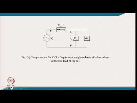
Watch Passive Shunt and Series Compensations on YouTube.
Frequently asked questions
What is an externally fused capacitor bank?
It is a shunt capacitor bank in which a separate external fuse protects each capacitor unit in an individually fused arrangement. When that fuse clears a qualifying fault, the complete unit is disconnected.
Can the bank run after one external fuse operates?
Only if the approved design and protection study permit that condition. The remaining units may experience changed voltage stress, so operators must follow the specified alarm, trip, and maintenance procedure.
Is an external unit fuse the same as a bank fuse?
No. An individual unit fuse isolates a capacitor can, while a bank-level fuse can remove a phase or a larger assembly. Verify the actual protected boundary on the drawing.
Which fusing arrangement should I request?
Request the arrangement supported by the system study, maintenance requirements, environmental conditions, and supplier coordination data. There is no single best arrangement for every bank.