
 Zhejiang Hongyan Electric Co., Ltd.
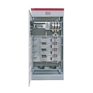
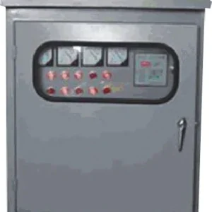
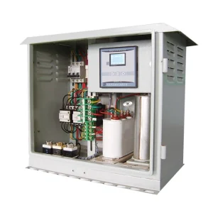
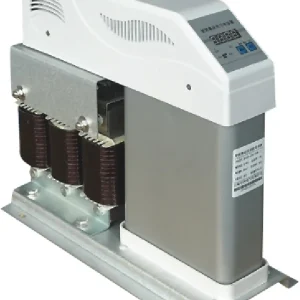
Third harmonic neutral current occurs when third-order currents from phase-to-neutral nonlinear loads reinforce one another in the shared neutral of a three-phase, four-wire system. The fundamental currents can cancel while these harmonic components remain. Consequently, three similar phase-current readings do not prove that the neutral is lightly loaded. The practical response is to measure the phase and neutral spectra, distinguish harmonic current from ordinary load imbalance, and select mitigation for the measured return-current path. This guide explains the mechanism, gives bounded calculation examples, and identifies the information needed for a technically useful equipment inquiry.
Why three balanced phases can still produce neutral current
In an ideal balanced sinusoidal system, the three fundamental phase currents have equal magnitude and a 120-degree separation. Their instantaneous sum is zero. A shared neutral therefore carries no fundamental current in that particular model. Real installations can depart from the model because the loads differ, the current waveforms are distorted, or both conditions occur together.
Many single-phase electronic loads draw current in pulses rather than as a smooth sine wave. Their periodic current can be described as a fundamental component plus harmonics. The third harmonic is at 150 Hz on a 50 Hz supply, or 180 Hz on a 60 Hz supply. Its phase relationship across three similar phase-to-neutral loads differs from the fundamental relationship.
For identical waveforms shifted by 120 fundamental degrees, the third-harmonic shift is 3 × 120 = 360 degrees. The three components are therefore aligned and reinforce one another in the neutral. This explanation assumes comparable harmonic magnitudes and the corresponding phase relationships. It should not be used as a universal arithmetic rule for dissimilar loads.
The discussion of neutral-current harmonics in the University of Waterloo research on distribution-system power quality explains why balanced nonlinear single-phase loads can still produce substantial neutral current. The distinction is between balanced fundamental currents and balanced total waveforms, not simply equal RMS meter readings.
Which harmonics add, and under what conditions?
Harmonic orders divisible by three are commonly described as triplen harmonics. The third, ninth, and fifteenth are particularly relevant in many waveforms with half-wave symmetry. In an ideal symmetrical set of phase-to-neutral nonlinear loads, these components can be zero sequence: they have the same phase relationship across the three phases and a return path through the neutral.
Do not assume that every third-harmonic component in every network has exactly that relationship. Unbalanced loads, supply distortion, differing controls, and connections can change the sequence content. For a measured installation, combine the three phase-current phasors separately at each harmonic order. Then combine different-frequency neutral components using RMS methods.
The connection is essential. A three-wire, line-to-line load does not directly deliver current into a neutral conductor it is not connected to. Transformer winding connections and other return paths can alter where zero-sequence current flows. Diagnose the actual one-line diagram before attributing a hot neutral to a nearby drive or specifying a filter.
Simple neutral-current calculations
At any instant, the neutral return current equals the negative of the sum of the three phase currents, with signs determined by the measurement convention. At harmonic order h, use the phasor sum IN,h = |IA,h + IB,h + IC,h|. If three equal third-harmonic components are aligned and each is I3, their neutral component is 3I3.
For steady periodic waveforms without a DC component, different-frequency components combine as IN,rms = √(IN,1² + IN,3² + IN,5² + …). This is not the arithmetic addition of all reported harmonic magnitudes. A recorder must have adequate bandwidth and an appropriate calculation method for the waveform being investigated.
| Illustrative equal phase components | Calculated phase RMS current | Calculated neutral RMS current | Meaning |
|---|---|---|---|
| 40 A fundamental; no harmonics | 40 A | 0 A | Ideal balanced sinusoidal case. |
| 40 A fundamental; 10 A third harmonic | √(40² + 10²) = 41.2 A | 3 × 10 = 30 A | Phase RMS readings are equal, but neutral current is substantial. |
| 20 A fundamental; 15 A third harmonic | √(20² + 15²) = 25 A | 3 × 15 = 45 A | Neutral RMS current exceeds each phase RMS current. |
These are ideal calculations using only the stated components. They are not measurements, conductor ratings, or acceptable operating limits. The fundamental components are assumed to cancel, and the third-harmonic components are assumed aligned. Additional harmonics and fundamental imbalance must be included in a real assessment.
Separate harmonic loading from ordinary phase imbalance
Redistributing single-phase loads can reduce the fundamental neutral current caused by unequal phase loading. It does not necessarily remove the zero-sequence harmonic components from similar nonlinear loads. A neutral can therefore remain heavily loaded after the phase RMS readings have been made more equal.
Start with the neutral spectrum. A strong fundamental component points toward imbalance or another issue requiring investigation. A strong third-harmonic component points toward the relevant nonlinear phase-to-neutral loads and their return-current path. Both can be present, so correcting one condition does not prove the other has been resolved.
Also examine the measurement setup and physical circuit. Shared neutrals, unintended parallel return paths, incorrect conductor identification, loose connections, and sensor limitations can produce misleading conclusions. High temperature at one termination can indicate a local connection problem in addition to the current duty. It should not automatically be diagnosed as a need for harmonic equipment.
Measure amperes and operating conditions, not only THD
Current THD uses the fundamental current as its reference. Where the neutral fundamental is small, neutral THD can become a very large percentage without conveying the actual thermal loading. Report the neutral RMS amperes and harmonic amperes alongside any percentage. The ampere values make the equipment duty easier to assess.
Log phase and neutral currents over representative operating periods. Include the number and type of electronic loads operating, shift changes, UPS operating modes, lighting conditions, and any alternative supply configurations. An isolated measurement during light occupancy may miss the condition that controls neutral loading.
Record the three phase-to-neutral voltages, relevant voltage distortion, current spectra, and the exact sensor locations. Include the conductor arrangement and transformer connection. A portable instrument placed at the wrong distribution level can describe a different mixture of loads from the circuit actually experiencing the problem.
The published scope of IEEE 519 addresses steady-state harmonic quality at the point of common coupling. That assessment does not replace an internal neutral-conductor loading and protection assessment. Specify separately where harmonic performance is required and which conductors and components need evaluation.
Choose mitigation for the return-current problem
Correct distribution and connection problems first
If fundamental imbalance or a defective connection is demonstrated, address that cause through the responsible electrical team. Review the actual conductor duty and protection against the governing installation requirements. A filter cannot restore a damaged termination or make an inadequately selected conductor acceptable by assumption.
Evaluate equipment designed for zero-sequence current
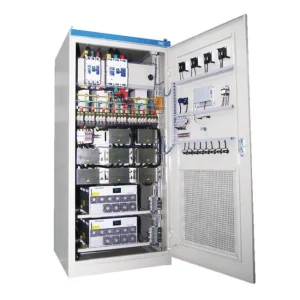
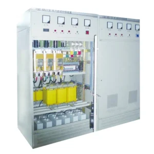
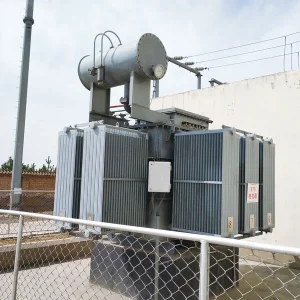
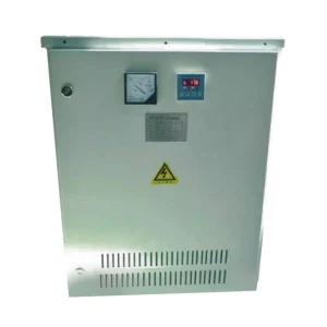
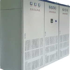
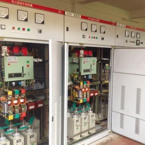
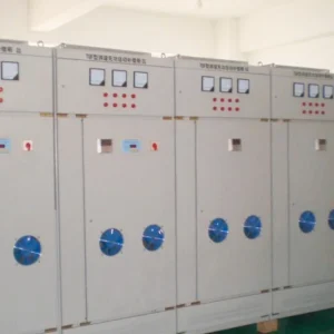
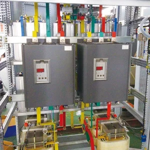
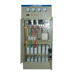
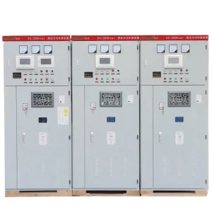
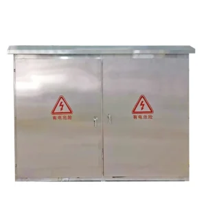
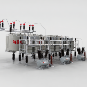
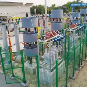
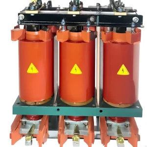
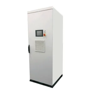
A zero-sequence mitigation device may be relevant when the measurements establish a corresponding neutral-current duty. Ask which components it targets, where it is connected, how its current rating is defined, and what the remaining neutral current will be under the agreed load conditions. Obtain the applicable drawings rather than inferring a connection from the product photograph.
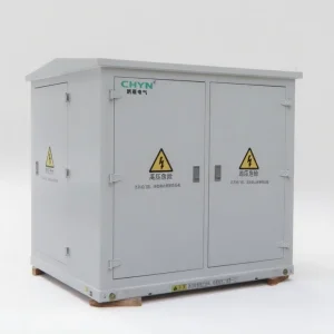
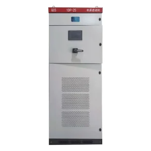
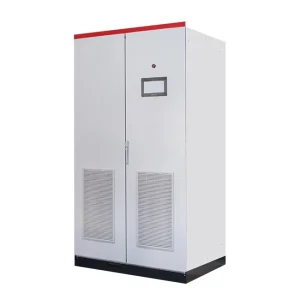
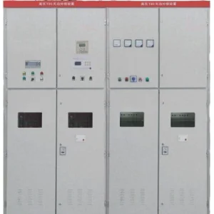
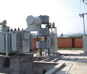
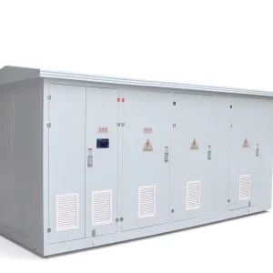
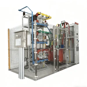
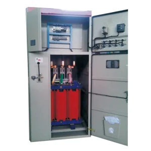
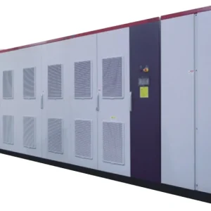
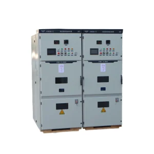
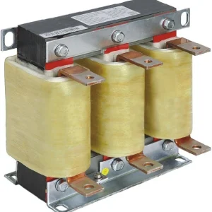
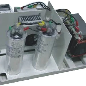
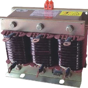
CHYN's HYLX zero-sequence current absorber is the relevant product family for that inquiry. The enquiry should include measured harmonic amperes, circuit arrangement, and the required operating envelope. Do not treat a general percentage suppression claim as a guaranteed result on an unmeasured circuit.
Check active-filter topology and simultaneous duties
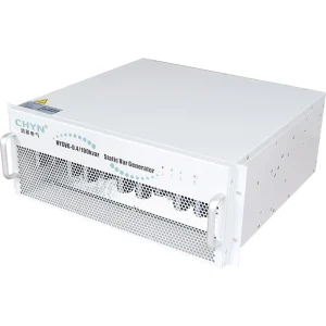
Where active filtering is considered, establish whether the proposed topology actually supports the required neutral-current compensation. A three-wire unit and a unit designed for four-wire neutral compensation are not interchangeable for this duty. Confirm phase and neutral ratings, CT arrangement, harmonic selection, control priorities, and environmental derating.
Reactive compensation and harmonic compensation can share a converter's available current. Use the existing SVG versus active harmonic filter selection guide to separate those functions. Improving displacement power factor does not, by itself, establish that the measured third-harmonic neutral current has been reduced.
Acceptance testing: verify the neutral and the process
Record a baseline before the corrective work and compare the result under similar load conditions afterward. Check the neutral RMS current, individual harmonic currents, phase currents, relevant temperatures, and any process symptoms. A lower percentage distortion at one point is not sufficient if the affected neutral still carries an unsuitable current.
Agree on the measurement location, operating states, sensor method, monitoring period, and target before ordering. Where loads vary, include the important combinations rather than testing only one favorable condition. Retain event records and configuration settings so later expansion can be assessed against a known baseline.
For the underlying current-injection principle, see how an active harmonic filter works. For a broader plant investigation, use the guide to causes of power quality problems. The present article's focus is the neutral return current, rather than every possible power-quality symptom.
Information to send with an inquiry
- Provide the one-line diagram, nominal voltage and frequency, earthing arrangement, transformer connection, and neutral distribution.
- Attach phase and neutral RMS amperes, fundamental and harmonic amperes, voltage data, and representative operating logs.
- Identify the affected conductor or equipment, physical symptoms, sensor positions, and any confirmed connection defects.
- State the target neutral-current duty, performance location, required operating states, and future load changes.
- Request the proposed topology, ratings, connection and sensing drawings, protection requirements, and acceptance method.
The useful procurement question is not simply how to eliminate the third harmonic. It is how to reduce the demonstrated neutral-current duty without overlooking fundamental imbalance, other harmonics, connection problems, and the rest of the distribution system.
Further learning: third harmonics and the neutral
The educational sample below, “Harmonic Sample - Third Harmonics and Neutral Currents,” is from Brainfiller and electrical educator Jim Phillips. It illustrates the harmonic relationship; it does not replace a site assessment or endorse a commercial mitigation product.
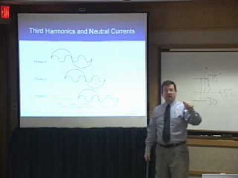
Watch Harmonic Sample - Third Harmonics and Neutral Currents on YouTube.
Frequently asked questions
Why do third harmonics add in the neutral?
For identical phase-to-neutral waveforms shifted by 120 fundamental degrees, the third-harmonic shift is 360 degrees. The aligned components reinforce one another in the neutral rather than cancel.
Can neutral current exceed phase current?
Yes. With an ideal balanced 20 A fundamental and aligned 15 A third-harmonic component on each phase, phase RMS current is 25 A while neutral RMS current is 45 A. Real circuits require the complete measured spectrum.
Will balancing the phase loads eliminate harmonic neutral current?
Not necessarily. Balancing can reduce fundamental neutral current, while zero-sequence harmonic components from comparable nonlinear phase-to-neutral loads can remain.
Is a high neutral THD percentage enough to select a filter?
No. Report neutral RMS amperes, harmonic amperes, phase data, connection details, and operating conditions. A small fundamental reference can make the THD percentage misleading.