
 Zhejiang Hongyan Electric Co., Ltd.
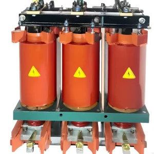
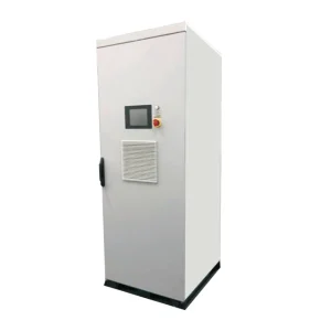
Comparing a thyristor vs contactor switched capacitor bank is mainly a decision about switching duty and load behavior. Capacitor-duty contactors can suit loads whose reactive demand changes slowly enough for the complete switching and discharge sequence. Thyristor switching can suit frequent, rapid changes when its sensing, firing logic, capacitor condition, and thermal design support that duty. Neither method makes capacitor steps continuously variable or automatically removes harmonics. Select the bank from its measured reactive-power profile, step sizes, harmonic environment, required switching frequency, protection, and acceptance criteria.
What changes when the switching device changes?
A mechanically switched step uses contacts to connect or disconnect a capacitor branch. The device must be suitable for capacitor duty, including the expected inrush and switching conditions. A standard current rating for a different load category is not sufficient evidence that a contactor is suitable for the proposed bank.
A thyristor-switched step uses semiconductor devices and controlled triggering. There are no mechanical switching contacts in the semiconductor current path, but the assembly still requires cooling, protection, sensing, suitable capacitors, and a defined operating sequence. Other isolation and switching devices can remain in the complete panel.
Middle East Technical University's research on thyristor-switched shunt capacitors investigates multiple topologies and compares thyristor switching with electromechanical contactors. It illustrates why the complete branch and control arrangement matter; one product's prototype results cannot be transferred to an unrelated commercial panel.
This comparison focuses on low-voltage industrial power-factor-correction duties. A transmission SVC, a thyristor-controlled reactor, and a low-voltage capacitor switching module have different design contexts even when all use thyristors.
A practical comparison of switching duties
| Selection question | Capacitor-duty contactor switching | Thyristor capacitor switching |
|---|---|---|
| How fast does the load change? | Assess whether the complete switching and discharge cycle can follow it. | Assess sensing, decision, firing opportunity, and the permitted repeat-switching duty. |
| What limits repeated operation? | Electrical and mechanical endurance, inrush duty, discharge requirements, and wear. | Thermal duty, current capability, protection, firing conditions, and branch limitations. |
| What must maintenance inspect? | Approved contactor condition, connections, discharge system, capacitors, and protection. | Cooling, semiconductor protection, sensing and trigger circuits, capacitors, and isolation provisions. |
| Does the bank become continuously variable? | No. Output changes by the connected capacitor steps. | No. A conventional TSC also connects discrete steps. |
| What proves acceptable performance? | Measured response and step operation under the specified load profile. | Measured end-to-end response and thermal operation under the specified load profile. |
The table identifies engineering checks rather than assigning universal response times, operating lifetimes, or savings. Those values must come from the actual proposed equipment and its permitted application conditions.
Use the reactive-demand profile to choose the duty
A plant with a fairly steady group of motors can have a different switching requirement from welders, presses, cranes, or equipment with repeated short operating cycles. The important evidence is the measured variation in reactive demand, not simply the industry name attached to the facility.
Record the minimum, maximum, change rate, duration, and repetition of the relevant demand. Include low-load periods and transitions. A daily average can conceal short events that determine the switching duty, while one unusually severe event may not represent normal production.
Compare the time needed for the bank to make a useful correction with the time for which the load condition persists. If a condition lasts only briefly, a correction arriving after it has ended can be ineffective or create leading operation. A faster switch alone cannot fix a controller that averages or delays the signal inappropriately.
For a wider review of compensation architecture, refer to the low-voltage power-factor-correction panel design guide. The present comparison concerns the switching method and its duty, rather than replacing the complete panel-design process.
End-to-end response is more than semiconductor switching time
The complete response includes measurement, signal processing, controller decisions, command transmission, the permitted switching opportunity, and the resulting branch current. A fast component specification does not automatically establish a fast system response at the point where performance is required.
A contactor-based system also has switching and reclosure constraints associated with the capacitor branch. Avoid prescribing a universal wait time copied from another panel. The manufacturer's discharge arrangement, residual-voltage limits, switch duty, controller settings, and protection determine the permitted sequence.
For thyristor switching, ask exactly how the controller determines a permissible connection condition. In an idealized switching analysis, reducing the voltage difference between the capacitor and the supply at connection reduces the excitation for an inrush transient. That is not always the same as firing at a zero crossing of the supply voltage.
A capacitor can retain voltage after disconnection. Its residual voltage and polarity therefore matter to the voltage across the switch. The proposed design should explain the sensing, firing, reclosing, and abnormal-condition handling without assuming every capacitor is uncharged at each command.
Fast switching does not make every step transient-free
Thyristor triggering can greatly improve the switching process when the branch and control are correctly engineered. Nevertheless, avoid an unconditional claim that every possible switching event has zero inrush or no voltage disturbance. Initial conditions, system impedance, component tolerances, failed sensing, and adjacent energized steps can change the duty.
Specify the relevant energization and repeated-switching conditions, the expected voltage and current stress, and the proposed limiting or detuning components. Also define what happens when a device fails to switch, a sensing input is missing, or a capacitor step is faulty.
For the wider switching-stress mechanism, use the capacitor-bank switching-transients guide. A semiconductor switching choice should be supported by the same clarity about operating conditions that is expected for a mechanical arrangement.
Step size still determines compensation resolution
A conventional capacitor bank changes output in discrete steps regardless of whether a contactor or thyristor connects them. A fast 50 kvar step does not become a continuously adjustable 0–50 kvar source. If the load's required correction frequently lies between the available combinations, a faster switch cannot remove that resolution limit.
As a deliberately simple example, a 40 kvar correction request and a bank whose only available change is 25 kvar cannot be matched exactly by that single step size. Connecting one step leaves 15 kvar uncompensated; two steps provide 50 kvar and exceed the request by 10 kvar. The controller's permitted strategy depends on the plant's target and operating boundaries.
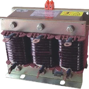
Capacitor output also varies approximately with voltage squared at a fixed frequency and unchanged capacitance. A step described as 25 kvar at its stated voltage does not necessarily deliver exactly 25 kvar at another bus voltage. A detuned branch adds further pairing considerations. The 7% detuned-reactor calculation guide explains that separate issue.
If the application requires continuous capacitive and inductive current control rather than discrete capacitive steps, compare the appropriate converter-based compensation option. Do not relabel a TSC bank as an SVG simply because its switching response is rapid.
Harmonics and thermal duty remain separate checks
Changing the switch does not change the basic fact that a capacitor branch interacts with the system's harmonic impedances. Measure the relevant voltage and current spectra, review any required reactors or filters, and specify the branch's continuous current and thermal duty. Thyristor switching is not a general substitute for harmonic filtering.
The scope of IEC 60831-1 includes self-healing shunt capacitors for AC systems up to and including 1000 V and relevant filter applications. Confirm the standard and component requirements for the actual voltage class; do not apply that scope automatically to a higher-voltage assembly.
Semiconductor conduction losses and cooling requirements deserve attention inside a panel. Ambient temperature, enclosure ventilation, contamination, loading, and adjacent heat sources affect the thermal design. A claim of no moving switching contacts does not mean the complete bank has no maintenance requirements or cooling components.
Review protective coordination, semiconductor protection where applicable, isolation arrangements, and the response to a failed step. A control command that blocks a thyristor is not, by itself, a maintenance isolation procedure.
Use CHYN product pages as enquiry routes, not proof of internal hardware
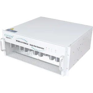
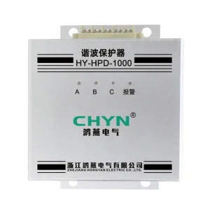
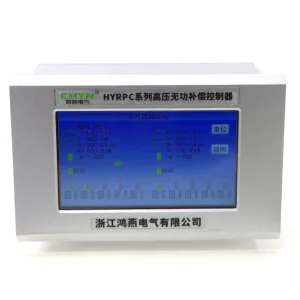
The HYTBBJ static reactive-compensation family and HYTBBD dynamic reactive-compensation family provide relevant starting points for discussing a proposed panel. Specify the required switching technology and duty explicitly, and obtain the approved component and control documentation.
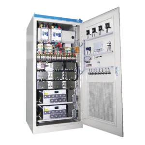
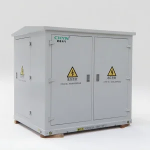
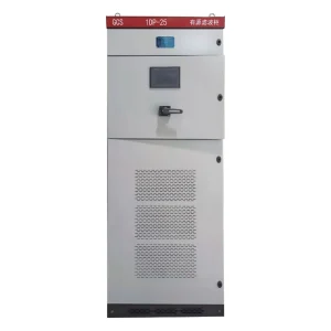
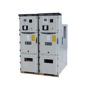
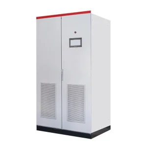
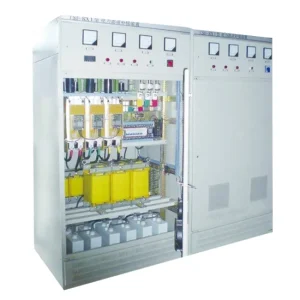
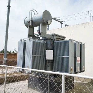
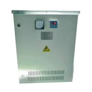
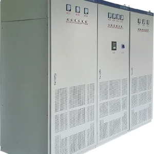
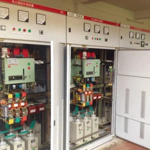
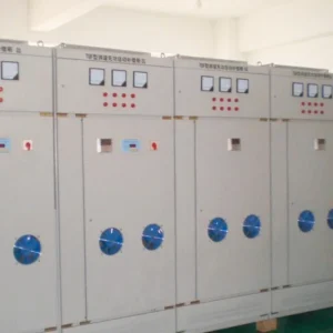
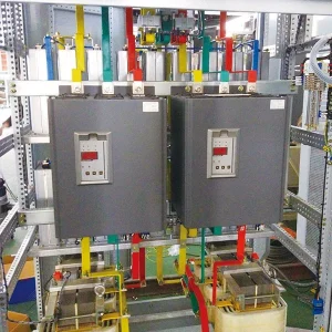
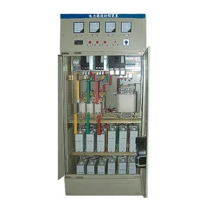
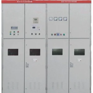
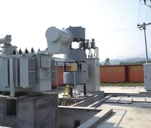
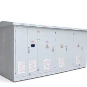
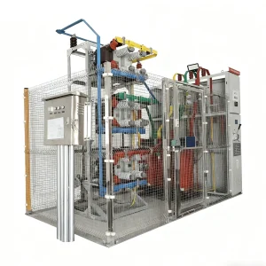
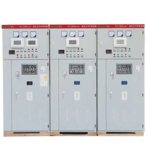
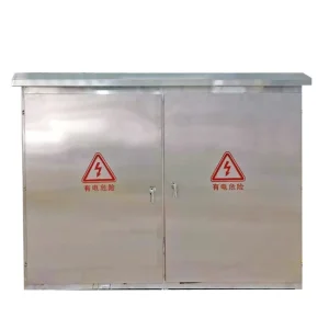
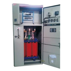
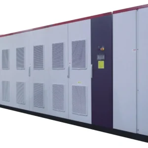
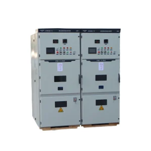
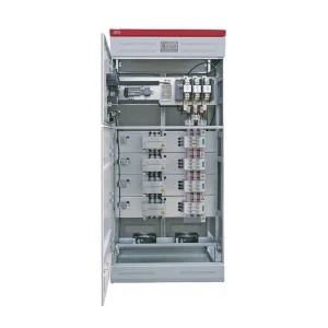
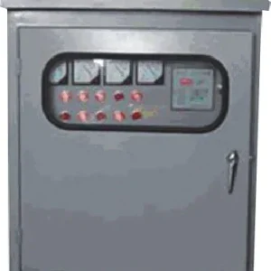
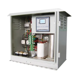
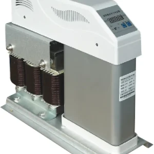
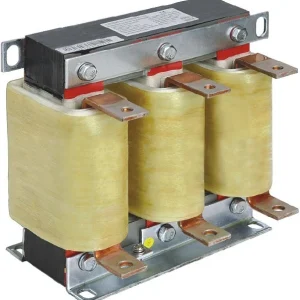
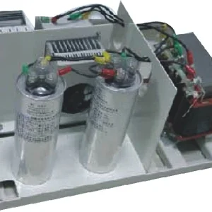
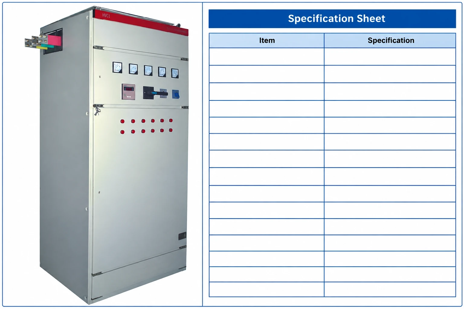
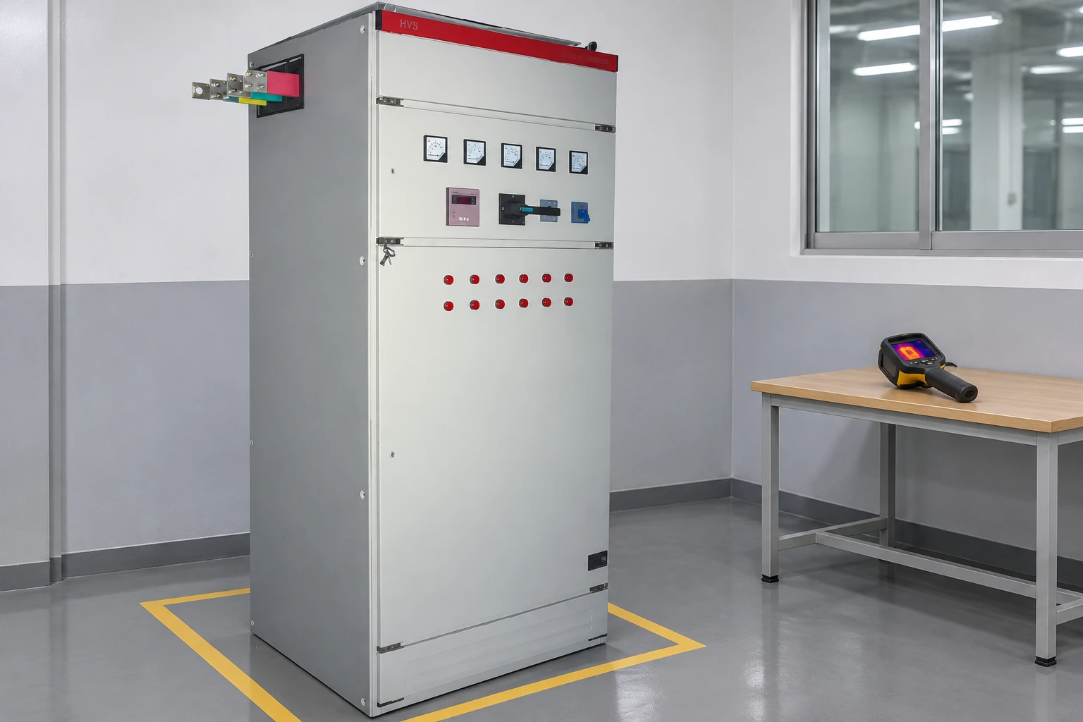
The cabinet illustrations use the existing HYTBBJ product photograph and preserve its visible arrangement. They do not identify an internal contactor or thyristor model, prove a response time, or represent a measured comparison. A family label or cabinet photograph cannot replace the proposed bill of materials and switching specification.
RFQ and acceptance checklist
- Provide nominal and maximum voltage, frequency, transformer and source data, one-line diagram, and earthing arrangement.
- Attach the reactive-demand time profile, target operating range, low-load conditions, and expected switching repetition.
- State required net kvar, step combinations, capacitor/reactor pairing, and harmonic measurements.
- Request the exact switching device, permitted duty, sensing and firing logic, discharge and reclosure conditions, protection, and cooling requirements.
- Agree a test of the complete response, step current, repeated operation, thermal behavior, alarms, and recovery under representative production conditions.
The best comparison demonstrates that the proposed complete bank can follow the actual load without exceeding its electrical and thermal duties. It does not rely on a device-speed headline or a promise that faster switching solves every power-quality problem.
Further learning: thyristor-switched capacitors
NPTEL IIT Guwahati's lesson “Lec 19: Thyristor Switch Capacitor (TSC)” explains the circuit principle. Its academic power-system context is useful background; it does not certify a commercial low-voltage panel or prescribe field wiring.
Watch Lec 19: Thyristor Switch Capacitor (TSC) on YouTube.
Frequently asked questions
When is thyristor switching useful for a capacitor bank?
It can be useful for frequent, rapid reactive-demand changes when the complete sensing, control, branch, protection, and thermal design support that duty.
Does thyristor switching make capacitor output continuously variable?
No. A conventional thyristor-switched capacitor bank still changes output through discrete capacitor steps. Faster switching does not remove the step-size limit.
Is supply-voltage zero crossing always the correct instant to switch?
No. Capacitor residual voltage and polarity affect the voltage across the switch. The approved sensing and firing strategy must account for the actual branch conditions.
Can a thyristor-switched bank replace harmonic filtering?
Not automatically. Harmonic loading and system resonance require their own assessment, including any necessary reactors or filters. Switching technology alone does not establish harmonic performance.