
 Zhejiang Hongyan Electric Co., Ltd.
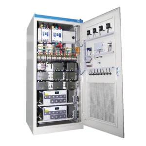
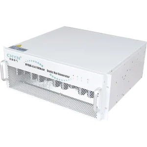
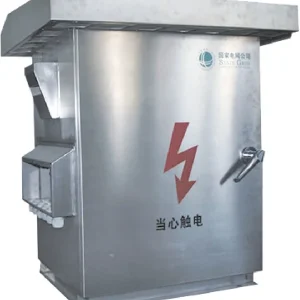
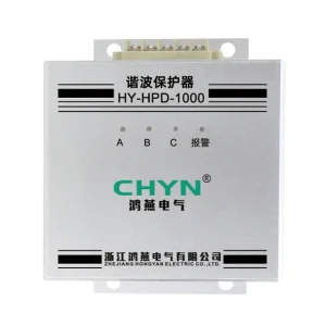
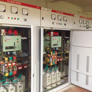
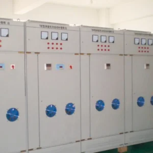
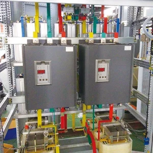
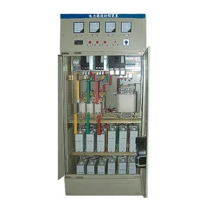
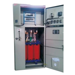
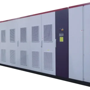
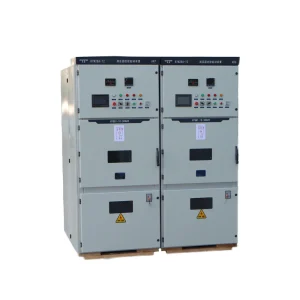
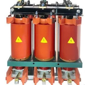
Dynamic voltage restorer bypass protection must provide a defined current path when a downstream fault, excessive overload or equipment failure prevents normal voltage injection. The bypass and protective devices need coordinated ratings and operating sequences; a fast transfer claim alone does not establish that coordination. Start with the actual circuit, identify which components carry current in each mode, and verify the complete clearing sequence against their limits. Maintenance bypass needs its own isolation procedure. A DVR can improve voltage during an upstream sag, but it cannot make a faulted downstream circuit healthy or guarantee an uninterrupted process during every bypass event.
Separate voltage correction from fault protection
A DVR inserts a controlled voltage in series with the protected supply path. That makes the current passing through its series equipment important even when the injected voltage is relatively small. Normal load current, transformer energization, motor starting and downstream short circuits represent different duties. A specification focused only on sag depth and compensation duration leaves these current duties unresolved.
The parent guide to voltage-sag ride-through specifications covers the disturbance envelope. This article addresses the associated protection path. Keep the two requirements connected: the protection must preserve equipment safety, while the process owner defines what interruption or voltage excursion can be tolerated during an event.
In his Aalborg University thesis, Design and Specification of the Dynamic Voltage Restorer, John Godsk Nielsen discusses electronic and mechanical bypass arrangements and the need to maintain a load-current path during faults, overloads and service. The practical implication is to request a topology-specific protection explanation rather than applying one generic switch sequence to every DVR.
Trace the current path in every operating mode
Ask for a power-circuit drawing that distinguishes the injection transformer, converter, electronic bypass, mechanical devices and isolation points. Vendor terminology varies. A switch described as a bypass may short a transformer winding, bypass a complete series section or provide a separate route around the system. Those actions create different current paths and isolation boundaries.
For each mode, the drawing should show which devices are conducting, which are blocking voltage and which parts remain energized. Record normal standby, voltage injection, downstream fault response, converter failure, loss of control power and maintenance operation separately. An abbreviated single-line diagram can be useful for planning, but it may not contain enough detail to approve the switching sequence.
Do not substitute an illustration from a research paper for the offered circuit. Two designs may use similar labels while placing the switches on different transformer sides. Copying a switching instruction across those designs can create an invalid path. The manufacturer must document the sequence for the exact supplied arrangement and explain its interlocks.
Build an event matrix before comparing transfer times
| Event | Required design question | Evidence to request |
|---|---|---|
| Upstream voltage sag | Does injection remain within the permitted envelope? | Load-voltage record, injection limits and recovery behavior |
| Downstream short circuit | Which path carries fault current until clearing? | Fault study, bypass withstand limits and protective-device sequence |
| Large load inrush | Is this an allowed overload or a bypass trigger? | Time-dependent overload curve and trigger logic |
| Converter or control failure | What state results when normal control is unavailable? | Failure-mode description and approved functional test |
| Planned maintenance | Which conductors are isolated and which remain live? | Switching procedure, isolation drawing and interlock checks |
This matrix is an engineering review framework, not a universal switching instruction. Complete it with the supplier and the engineer responsible for the installation. If an event has no documented current path or defined final state, treat that omission as an unresolved design item before release for manufacture.
Define timing reference points consistently. Detection, bypass command, current commutation, mechanical closure and downstream clearing are separate events. A quoted transfer time may cover only one interval. Ask which interval was measured, under what current and voltage conditions, and whether the result includes the protected load's voltage disturbance.
Coordinate the bypass with downstream and upstream protection
Obtain the prospective fault current for the relevant locations and source configurations. A transformer-fed utility case can differ from generator operation or a bus-tie arrangement. Include the available study assumptions, protection settings and device characteristics. The design must consider the credible maximum duty as well as lower fault currents that can take longer to clear.
Compare the current-versus-time exposure with the applicable limits of every component in the path. Continuous current, short-time withstand, peak withstand, interrupting capability and semiconductor stress describe different constraints. A single ampere number cannot replace those checks. Where the supplier specifies an energy-related limit, the protection study should use a compatible method rather than assuming equal thermal behavior for unlike devices.
Confirm which protective device is intended to clear the fault first and what happens if it fails. A bypass can preserve a route for fault current while the breaker or fuse clears; that does not mean the bypass itself is a circuit breaker. Likewise, bypassing the converter does not automatically remove the fault from the downstream feeder.
Research into combined fault-current limiting and voltage restoration illustrates why the distinction matters. The original study Fault Current Limiter Dynamic Voltage Restorer with Reduced Number of Components proposes a specific dual-function topology and reports simulation and laboratory results. It is evidence that fault limiting is a design function requiring particular circuitry and control, not an inherent capability of every commercial DVR.
Check inrush, overload and repeated transfer behavior
A motor or transformer can produce a high current without a downstream short circuit. Provide measured or modeled starting characteristics and the expected repetition rate. The supplier should identify permitted injection duty, any intentional bypass threshold and the conditions for returning to normal operation. A threshold that protects the converter may still create a process interruption if chosen without the load requirements.
Repeated attempts to restore injection can also matter. Specify how the controller confirms that the fault or overload has ended, whether manual acknowledgment is required and how repeated unsuccessful transfers are handled. Ask for event records that distinguish an external disturbance from an internal alarm. Clear records help maintenance teams avoid repeatedly resetting a system into an unresolved condition.
Review the DC-link and energy-storage behavior during abnormal events. The separate article on DVR energy-storage sizing addresses duration and energy. Here the question is protective behavior: what limits are monitored, how the system responds when energy is unavailable, and whether re-entry is inhibited until the equipment is ready.
Specify maintenance isolation as a separate deliverable
A conducting bypass can supply the load while leaving parts of the DVR energized. It is therefore insufficient to label a system “bypassed” and assume it is safe to service. The isolation plan must identify all power and control sources, stored-energy provisions, verification points and any backfeed paths. Only qualified personnel should perform the approved procedure.
Ask whether the design supports the intended maintenance scope. Replacing a control component, accessing converter equipment and working on the series transformer may require different boundaries. A route that bypasses only part of the system may not permit work on every part. Document those limitations before the owner commits to a maintenance strategy.
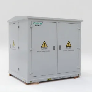
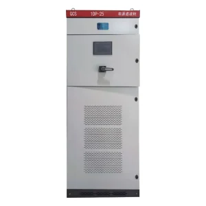
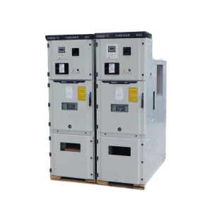
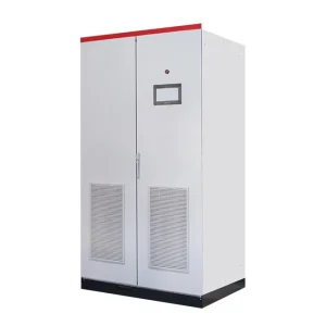
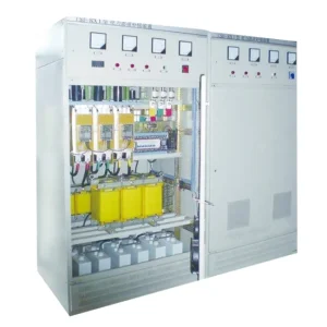
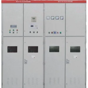
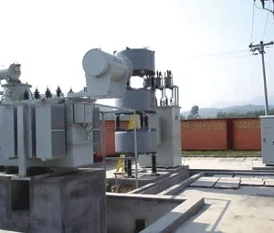
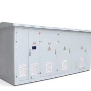
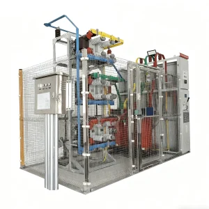
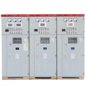
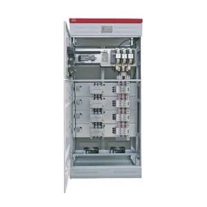
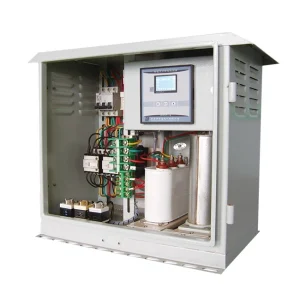
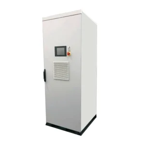
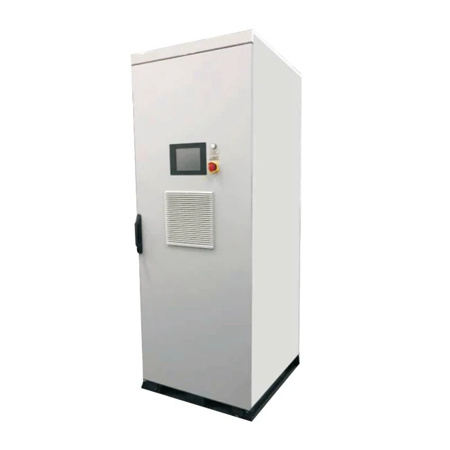
Interlocks should prevent prohibited switching combinations, and their verification should form part of the factory or site functional checks. Do not infer a complete isolation arrangement from a cabinet photograph. The CHYN HYDVR product family is the starting point for an application discussion; the quotation and approved drawings establish the actual supplied protection and bypass scope.
Agree on evidence for factory and site acceptance
Request the applicable design evidence, device ratings, protection settings, sequence descriptions and test procedures before delivery. Some fault-duty claims rely on documented design or type-test evidence rather than deliberately creating a site short circuit. Functional checks should use approved methods that verify logic and indications without exposing people or equipment to an uncontrolled fault.
For safe simulated inputs or manufacturer-approved tests, record the event trigger, mode indication, bypass command, device feedback and load-voltage response on a common time base. Verify alarms, loss-of-control-power behavior and return-to-service conditions within the agreed scope. An indicator changing color is useful feedback, but it is not by itself proof of the complete current-transfer process.
Keep a final event matrix with the as-built drawing and settings. Include any production restrictions during maintenance bypass and the person responsible for authorizing return to injection. Also review phase-angle jumps during DVR compensation when the process is sensitive to the voltage waveform at transfer or recovery. Acceptance should address the load's actual tolerance, not simply whether the cabinet remained powered.
Further learning: the fault study behind coordination
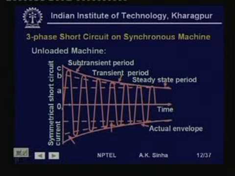
This NPTEL short-circuit analysis lecture explains the calculation context used in protection studies. It is background learning rather than a DVR switching procedure or a demonstration of the CHYN bypass design.
Watch the NPTEL lecture on YouTube.
Frequently asked questions
Does a DVR bypass clear a downstream short circuit?
A bypass can provide an alternative current path while the designated protective device clears the fault. Do not assume the bypass itself interrupts fault current unless the supplied design explicitly provides that function.
Is static bypass equivalent to maintenance isolation?
No. Bypass can leave equipment energized. Maintenance requires an approved isolation procedure for the actual power circuit, control supplies and stored-energy sources.
Can every DVR limit fault current?
No. Combined fault-current limiting requires an appropriate topology and control strategy. Confirm the function in the offered design rather than inferring it from the DVR label.
What should a bypass transfer-time claim include?
Request the timing reference points, test conditions and associated load-voltage record. Detection, current transfer, mechanical closure and downstream fault clearing are separate intervals.